User’s Manual of WGS Managed Series
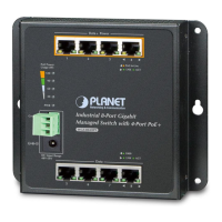
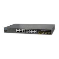
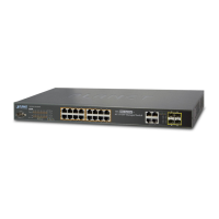
■ Gigabit TP Interface
10/100/1000BASE-T copper, RJ45 twisted-pair: Up to 100 meters.
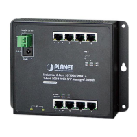
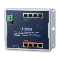
■ 100/1000BASE-X SFP Slots (WGS-4215-8T2S and WGS-4215-8P2S only)
Each of the SFP (Small Form-factor Pluggable) slots supports dual-speed, 1000BASE-SX/LX or 100BASE-FX
- For 1000BASE-SX/LX SFP transceiver module: From 550 meters (multi-mode fiber) to 10/30/50/70/120 kilometers
(single-mode fiber).
- For 100BASE-FX SFP transceiver module: From 2 kilometers (multi-mode fiber) to 20/40/60 kilometers (single-mode
fiber).
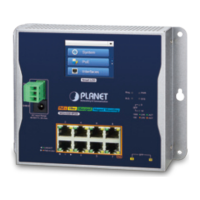
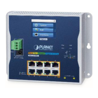
■ AC/DC Power Receptacle
The Managed Switch features a strong dual power input system (terminal block and DC jack) incorporated into customer’s
automation network to enhance system reliability and uptime.
Power Input
Range
Model
3-pin Terminal Block DC Jack
WGS-804HPT 48~54V DC 48~54V DC
WGS-4215-8T
12~48V DC,
24V AC
12~48V DC,
24V AC
WGS-4215-8T2S
12~48V DC,
24V AC
12~48V DC
WGS-4215-8P2S
48~54V DC 48~54V DC
WGS-4215-16P2S 48~54V DC 48~54V DC
To install the 3-pin Terminal Block Connector on the Wall-mount Managed Switch, follow the following steps:
Step 1: Insert positive DC power wire into V+, negative DC power wire into V-, and grounding wire into Ground.
Step 2: Tighten the wire-clamp screws for preventing the wires from loosening.
Power Notice:
In some areas, installing a surge suppression device may also help to protect your Managed Switch
from being damaged by unregulated surge or current to the Managed Switch.
 Loading...