12
463X Chlorine Systems Manual
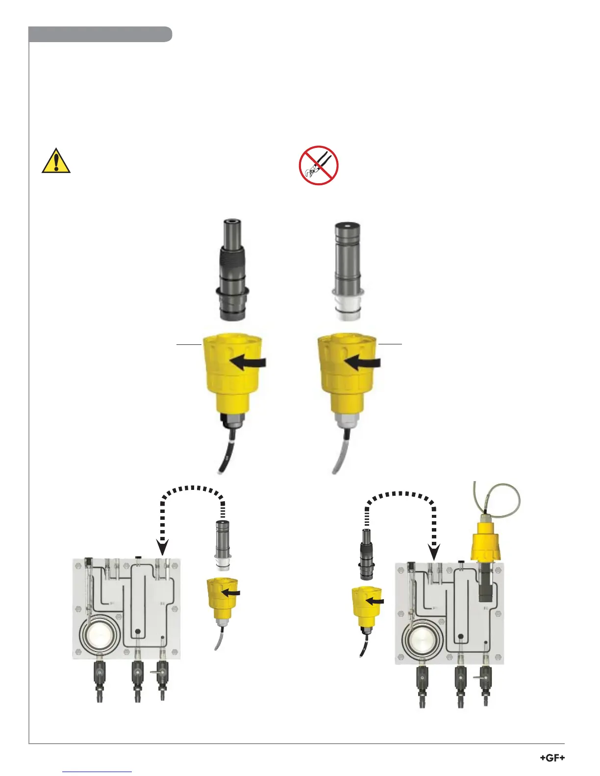
• Remove sensor access plugs from the fl ow cell (pg. 4, Figure 1).
Note: Chlorine Sensor Preparation must be completed prior to installation, see page 11.
• Holding the 3-2750-7 (159 001 671) or 3-2650-7 (159 001 670) electronics inverted, open the DryLoc
®
connector by
turning the upper locking ring ¼-turn counter-clockwise.
• Insert the electrode facing up. Turn the locking ring ¼-turn clockwise to lock the electronics in place.
• The mechanism will “click” when it is locked.
• Install the complete assembly into the fl ow cell and ensure the key on the electrode aligns with the key slot on the fl ow cell.
DryLoc
®
Connection to Sensor Electronics
Locking Ring
Locking Ring
LockLock
3-2724-00
(159 001 545)
pH electrode
3-2630-X
FCL electrode
3-2750-7
(159 001 671)
pH electronics
3-2650-7
(159 001 670)
Amperometric Electronics
3-2632
ClO
2
electrode
Lubricate O-rings with
a non-petroleum
based, viscous
lubricant (grease)
compatible with the
system.
Avoid skin or eye contact with electrolyte solution.
Wear rubber gloves and goggles.
Material Safety Data Sheets (MSDS) are available
online at www.gfsignet.com.
Do Not Use Lubricant or Sealing Tape on Threads.
Do Not Overtighten. Do Not Use Tools.
Do Not Drop or Strike the Membrane.
Signet 3-2724-00
(159 001 545)
Flat pH Electrode
Signet 3-2630-X
Signet 3-2632
Chlorine Electrode
Signet 3-2650-7
Electronics
Signet 3-2750-7
pH Electronics
Sensor Installation