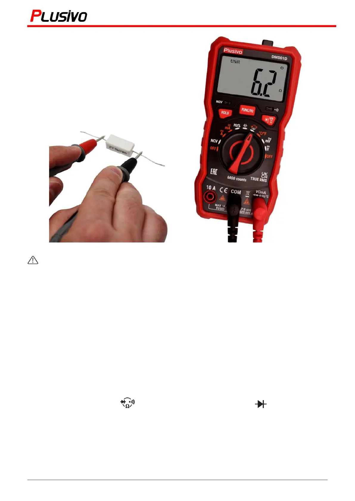
The resistance measured in this figure is 6.2 Ω
To avoid damage to the meter or device under test, allpower to the circuit under test must be
turned off before measuring resistance, and all high voltage capacitors must be fully discharged.
Notes:
● The resistance value measured on the circuit is usually different from the rate resistance.
● To measure the low resistance accurately, please short- circuit the two test pens to read out the
short-circuit resistance of the test leads, and subtract it by the readings to get an accurate
resistance value.
● In the 60 MΩ range, readings stabilize after a few seconds, which is normal for high resistance
measurements.
● When the meter is not connected to the circuit, the display shows "OL", which indicates that the
measurement value is out of the measurement range.
7.3 Diode Measurement
Test a diode outside the circuit:
1. Turn the rotary switch to position and press "FUNC-Hz" to select
2. Connect the black test pen to the “COM” input socket and the red test pen to the “V-Ω” input
socket.
3. Connect the black test pen and the red test pen to the negative and positive electrodes of the
diode under test.
4. The meter will display the forward bias value of the diode under test. If the polarity is reversed,
"OL" will be displayed.
14
Mastering the Art of Measurement (DM501D Digital Multimeter) r.01 www.plusivo.com