Do you have a question about the PMC PH and is the answer not in the manual?
Important safety instructions and warnings for using the PH Series Proportioner.
Details the limited warranty period, coverage for defects, and proof of purchase requirements.
Covers customer responsibility for product maintenance and warranty exclusions.
States warranty disclaimers, liability limitations, and exclusive warranty provisions.
General safety advice and procedures for operating the PH Series Console.
Explanation of warning, caution, and note symbols used in the manual.
Awareness of material, pressure, temperature, and crushing hazards, and required PPE.
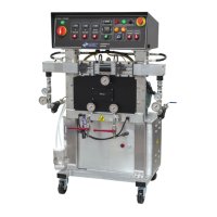
Identification of components on the front panel of the 220 VAC, 1-Phase unit.
Detailed list of parts and descriptions for the 220 VAC, 1-Phase front panel.
Diagram showing component layout on the bottom plate of the 220 VAC, 1-Phase unit.
Diagrams illustrating internal component placement and connections for the 220 VAC, 1-Phase unit.
Detailed list of internal components and their specifications for the 220 VAC, 1-Phase unit.
Diagram illustrating the point-to-point wiring for the incoming power supply.
Diagram showing point-to-point wiring for heater circuits, including temperature controllers.
Diagram illustrating point-to-point wiring for motor control circuits.
Diagram showing point-to-point wiring for the 24 VDC power distribution.
Diagram illustrating point-to-point wiring for pump and solenoid control circuits.
Diagram showing point-to-point wiring for the pressure balance control system.
Schematic representation of incoming power distribution using ladder logic.
Schematic representation of heater circuits using ladder logic.
Schematic representation of motor control circuits using ladder logic.
Schematic representation of 24 VDC power distribution using ladder logic.
Schematic representation of pump circuits using ladder logic.
Schematic representation of pressure balance control using ladder logic.
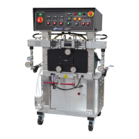
Identification of front panel components for the 220 VAC, 3-Phase unit.
List of parts and descriptions for the 220 VAC, 3-Phase front panel.
Diagram showing component layout on the bottom plate for the 220 VAC, 3-Phase unit.
Diagrams illustrating internal component placement for the 220 VAC, 3-Phase unit.
Detailed list of internal components for the 220 VAC, 3-Phase unit.
Diagram for point-to-point wiring of incoming power for the 3-phase unit.
Point-to-point wiring diagram for heater circuits in the 3-phase unit.
Point-to-point wiring diagram for motor control in the 3-phase unit.
Point-to-point wiring diagram for 24 VDC power in the 3-phase unit.
Point-to-point wiring diagram for pump circuits in the 3-phase unit.
Point-to-point wiring for pressure balance control in the 3-phase unit.
Ladder logic schematic for incoming power in the 3-phase unit.
Ladder logic schematic for heater circuits in the 3-phase unit.
Ladder logic schematic for motor control in the 3-phase unit.
Ladder logic schematic for 24 VDC power in the 3-phase unit.
Ladder logic schematic for pump circuits in the 3-phase unit.
Ladder logic schematic for pressure balance control in the 3-phase unit.
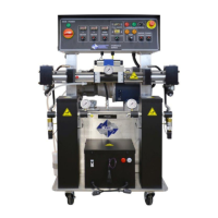
Identification of front panel components for the 400 VAC unit.
List of parts and descriptions for the 400 VAC front panel.
Diagram showing component layout on the bottom plate for the 400 VAC unit.
Diagrams illustrating internal component placement for the 400 VAC unit.
Detailed list of internal components for the 400 VAC unit.
Diagram for point-to-point wiring of incoming power for the 400 VAC unit.
Point-to-point wiring diagram for heater circuits in the 400 VAC unit.
Point-to-point wiring diagram for motor control in the 400 VAC unit.
Point-to-point wiring diagram for 24 VDC power in the 400 VAC unit.
Point-to-point wiring diagram for pump circuits in the 400 VAC unit.
Point-to-point wiring for pressure balance control in the 400 VAC unit.
Ladder logic schematic for incoming power in the 400 VAC unit.
Ladder logic schematic for heater circuits in the 400 VAC unit.
Ladder logic schematic for motor control in the 400 VAC unit.
Ladder logic schematic for 24 VDC power in the 400 VAC unit.
Ladder logic schematic for pump circuits in the 400 VAC unit.
Ladder logic schematic for pressure balance control in the 400 VAC unit.
| Brand | PMC |
|---|---|
| Model | PH |
| Category | Paint Sprayer |
| Language | English |