PL Hybrid (PL COMM & PL LT) Models Installation
PL Hybrid Systems consist of a PL COMM (Commander) Salt Chlorinator, and optionally
up to 4 x PL LT (Lieutenant) Salt Chlorinators.
The installation process for each individual unit is the same as for any other model Pool
Lab Salt Chlorinator, except that consideration must be given for the placement of multiple
cell housings if PL LT units are to be installed in the system.
The chlorinator cells can be arranged together in series or if there are multiple filtration
systems, they can be split between the systems. Always ensure the chlorinator cells are
plumbed into the water circuit after any heaters or solar systems to prevent damage to that
equipment.
The PL Hybrid system is also supplied with a dual port injector for connection of the acid
and liquid chlorine pump lines to a single location. This should be plumbed into the water
circuit AFTER the cell housing(s) and any heaters or solar equipment so that the injected
chemicals do not flow through these.
HYBRID MODELS DO NOT USE THE CELL HOUSING INJECTION PORTS.
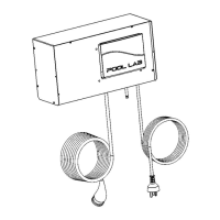
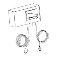
Install and connect the Pool Lab ASP as per the Owner's Manual supplied with that unit.
Ensure the ASP is installed after a filter, and before any heaters or solar system, and
before the cell housings and chemical injection points.
The ASP connects to the port labelled “ASP” on the PL COMM salt chlorinator.
Connecting the additional PL LT units
Each PL LT unit is supplied with a data cable, and the units daisy chain together so that
they are all connected to the PL COMM via an RS485 data bus.
– On the first PL LT unit this cable will go from the port labelled “COMM ( < LT)”, to
the port labelled “EXP/LT” on the PL COMM unit.
– On subsequent PL LT units this cable will go from the port labelled “COMM ( < LT)”,
to the port labelled “EXP (LT >)” on the previous PL LT unit.
If a Pool Lab EXP module is to be connected, this will connect to the “EXP (LT >)” port on
the last PL LT unit, or to the “EXP/LT” port on the PL COMM if no PL LT units are
connected.
Configuring the additional PL LT units
Each PL LT unit is supplied with 2 x configuration plugs. These are used to in the BUS
CONFIG ports to configure each PL LT unit with a unique 'address' or identifier number.
– The first PL LT unit does not require any configuration plugs: LIEUTENANT #1
– The second PL LT requires a plug in PORT A only: LIEUTENANT #2
– The third PL LT requires a plug in PORT B only: LIEUTENANT #3
– The forth PL LT requires a plug in both PORT A & B: LIEUTENANT #4
32