37EGW06-PCPEG-20140813
TM
TM
Section IV: Installation
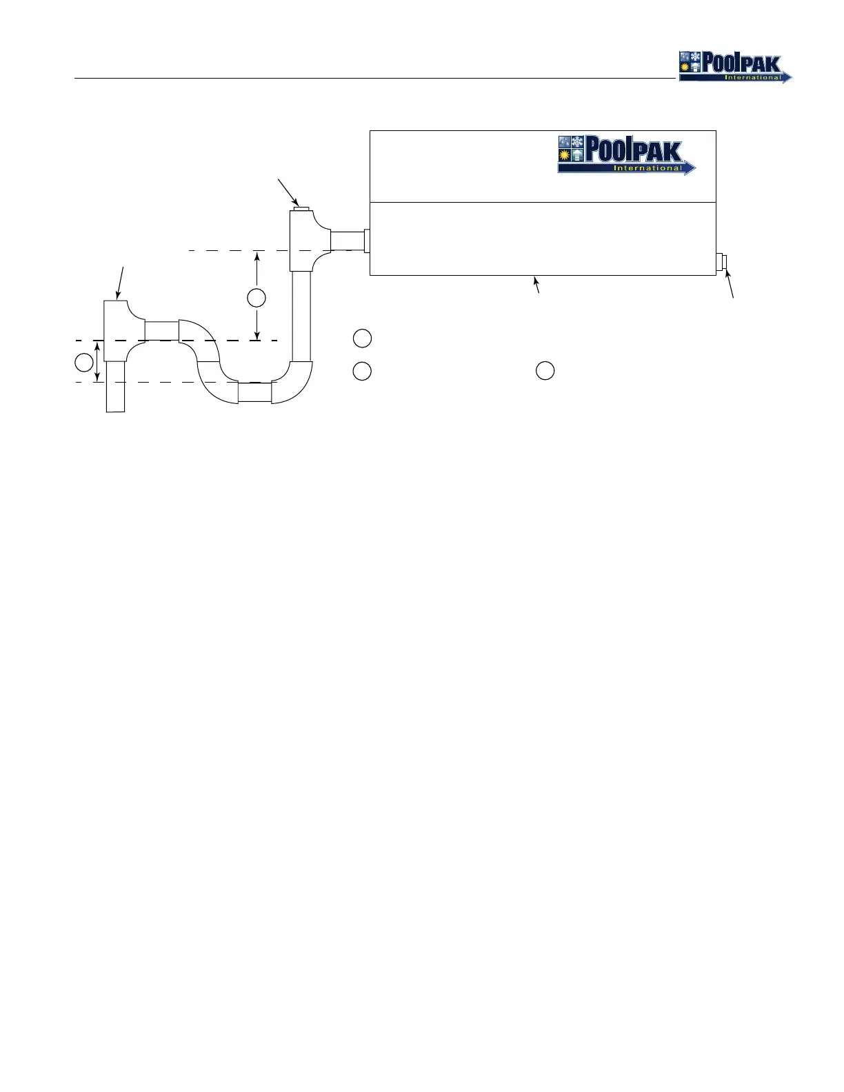
Figure 4-9. AWH and HCDH Condensate Trap
PCP_EG_NegPressCondPiping_20140122.eps
WATER COOLED CONDENSER
A standard option for PoolComPak™ units is an integral water-cooled condenser. For this option, all valves and
refrigerant piping is internal to the unit. No additional eld wiring is required. No additional refrigerant or oil charge is
required. Water piping connections are 1-1/4” MPT and labeled on the unit.
REMOTE AIR-COOLED CONDENSER
SPACE AND LOCATION REQUIREMENTS
The most important consideration which must be taken into account when deciding upon the locations of air-cooled
equipment is the provision for a supply of ambient air to the condenser, and removal of heated air from the condenser
area. Where this essential requirement is not adhered to, it will result in higher head pressures, which cause poor
operation and possible eventual failure of equipment. Units must not be located in the vicinity of steam, hot air, or fume
exhausts.
Another consideration which must be taken is that the unit should be mounted away from noise sensitive spaces and
must have adequate support to avoid vibration and noise transmission into the building. Units should be mounted over
corridors, utility areas, rest rooms, and other auxiliary areas where high levels of sound are not an important factor.
Sound and structural consultants should be retained for recommendations.
Walls or Obstructions
The unit should be located so that air may circulate freely and not be re-circulated. For proper air ow and access all
sides of the units should be a minimum of “W” away from any wall or obstruction. It is preferred that this distance be
increased whenever possible. Care should be taken to see that ample room is left for maintenance work through access
doors and panels. Overhead obstructions are not permitted. When the unit is in an area where it is enclosed by three
walls, the unit must be installed as indicated for units in a pit.
UNIT BASE
MINIMUM SCHEDULE 40 PVC
REMOVABLE
CLEANOUT
OPEN TEE
FOR VENT
AWH OR HCDH UNIT
PLUG THE
UNUSED
CONNECTION
WITH SUITABLE
PVC PLUG
1
2
4 INCHES MINIMUM OR MAX NEGATIVE STATIC
PRESSURE (INCHES W.C.) + 1 INCH
2 INCHES MINIMUM OR 1/2
1
1
2
TM
TM