36 EGW06-PCPEG-20140813
TM
TM
Section IV: Installation
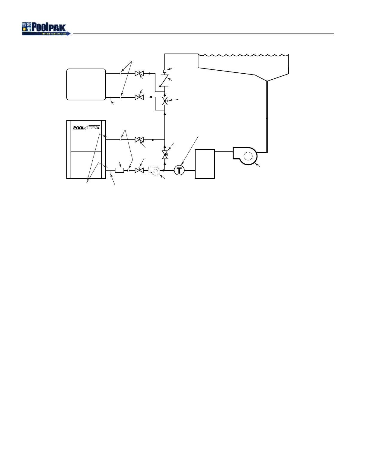
Figure 4-8. Typical Pool Water Piping Diagram (AWH and AWV Model Only)*
PCP_EG_PoolWaterConnectSchematic_20140305.eps
CONDENSATE DRAINS
Drain pans are connected to a common drain system and must be trapped for proper operation. For AWH and HCDH
units, a trap and piping must be supplied and installed by the customer. The trap depth must be a minimum of 6 inches
(See gure 4-9). For AWV and HCDV units a condensate trap is located inside the unit and the eld condensate piping
and overow drain must not have an additional trap.
Provisions MUST be made for disposal of condensate. Condensate from the dehumidier coil will have nearly the same
properties as the pool water itself. It is recommended that building materials subjected to the condensate and systems
used for its disposal are checked for compatibility. For drain piping use PVC plastic pipe minimum Schedule 40. The
drain line must be sloped to provide proper drainage.
Drain line exposed to outdoor ambient temperatures must be protected against freezing. Wrap lines with electric heat
tape (follow manufacturer’s instructions) controlled by an automatic thermostat set at a minimum of 35°F to protect
against freezing. Insulate all piping. Insulation must be sealed at all seams. Power for heat tape must be supplied external
to the PoolComPak™.
POOL
CHEMICAL
FEEDER
CHECK
VALUE
OPTIONAL
BOOSTER
PUMP IF
MAIN FILTER
PUMP IS A
2-SPEED OR
UNDERSIZED
BALL
VALVES
POOL
WATER
FILTER
MAIN
FILTER
PUMP
DRAIN
UNIONS
EXTERNAL
PRESSURE
TAP PORTS
UNIONS
AUXILIARY
POOL WATER
HEATER
DRAIN
BALL
VALVES
LOCKING
GLOBE
VALVE
LOCKING
GLOBE
VALVE
POOL WATER
TEMP. SENSOR
FC
Flow
Control