EN | 11
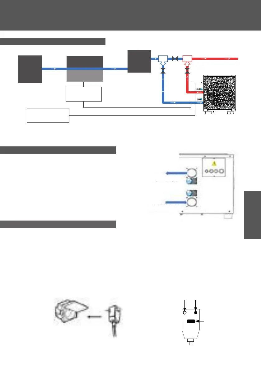
TO THE SPA
Spa heater
control relay
Wall plug
230V 16A 10mA
Filter
Control unit
Circulaon
pump
Electric heater
3. INSTALLATION
3.2 Installation diagram
The lter located upstream of the heat pump must be regularly cleared so that the water in the system
is clean, thus avoiding the operaonal problems associated with dirt or clogging in the lter.
Step 1: Screw the connectors for heat pump.
Step 2: Connect the water inlet and outlet.
3.3 Hydraulic connection
Pump's power plug integrates a 10mA dierenal circuit breaker.
Regularly test the correct operaon. In the event of successive triggering or doubts contact the
aer-sales service.
Before plugging in your heat pump, please ensure the electrical socket is properly grounded and
protected from rain as well as water projecons.
Press the RESET buon to start the heat pump. The power indicator lights up in red: the heat pump
is on.
3.4 Electrical connection
Test
Power
indicator
Reset
To the SPA To the SPA
From the SPA From the SPA