POWER ELECTRONICS
VS65
ANNEXE A. POWER CABINET OPERATION
45
Figure 8.5 Logic diagram of NPS II protection
Overload protection
If the current of phase A or phase C (or three phases) is larger than overload setting value, then
the timer is starting. The device can select the action between the warn and trip.
Figure 8.6 Logic diagram of Overload protection
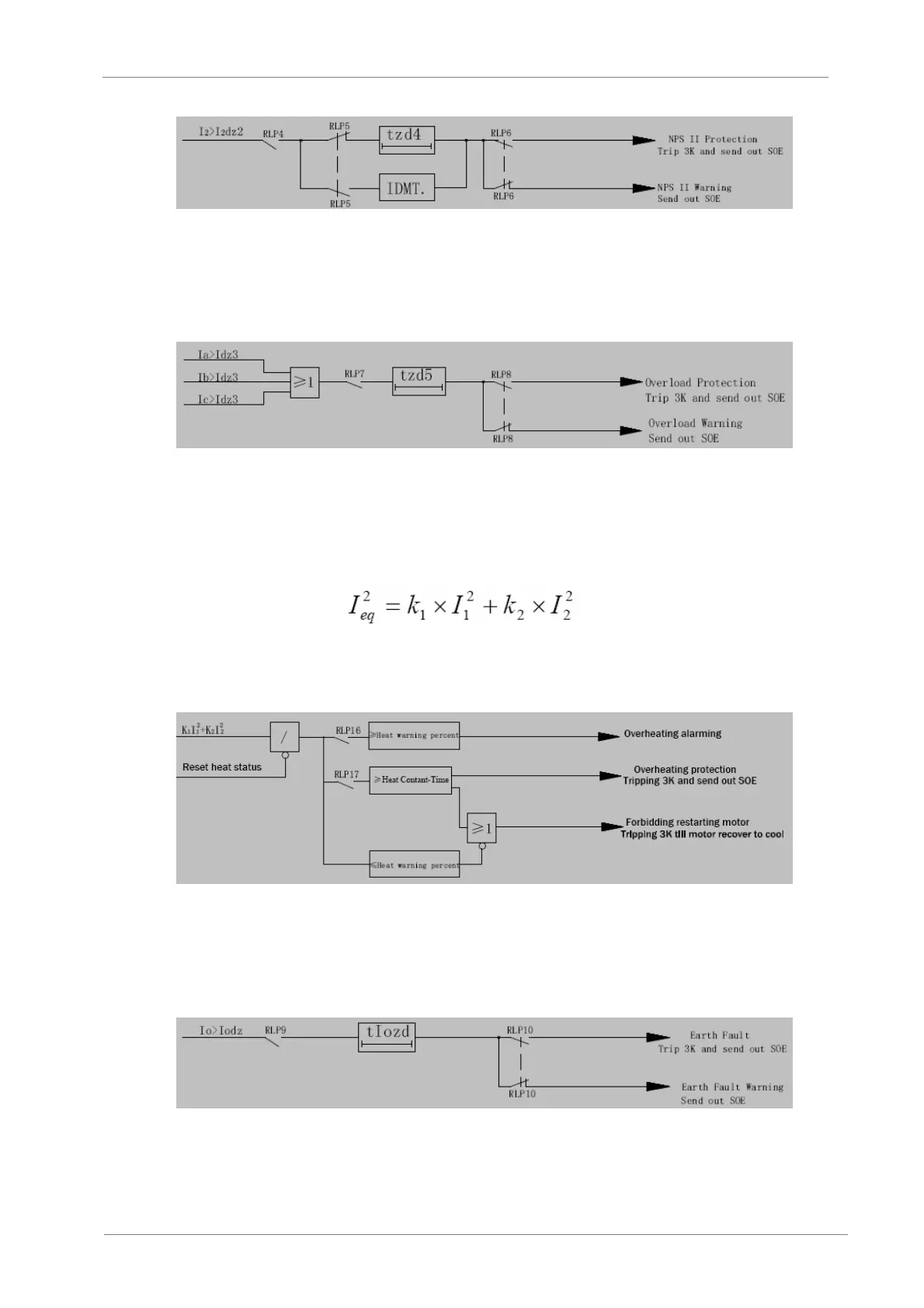
Thermal Overload protection
Thermal overload protection is used to prevent the motor from overheat. Considering the thermal
effect of positive-sequence current (I1) and negative-sequence current (I2), we build a formula as
below to simulate the process of the motor producing (Ieq) heat:
In the start-up time of the motor, K1=0.5 and after the start-up time, K 2=3 ~ 10.
After the device trip, the motor is forbidden to restart until the motor has return to the cool status
or press the “RES” key on the keypad.
Figure 8.7 Logic diagram of Overheat protection
Earth fault protection
If the zero sequence current is larger than the setting value, then the timer is starting. The device
can select the action between the warn and trip.
Figure 8.8 Logic diagram of earth fault protection