POWER ELECTRONICS
VS65
ANNEXE A. POWER CABINET OPERATION
47
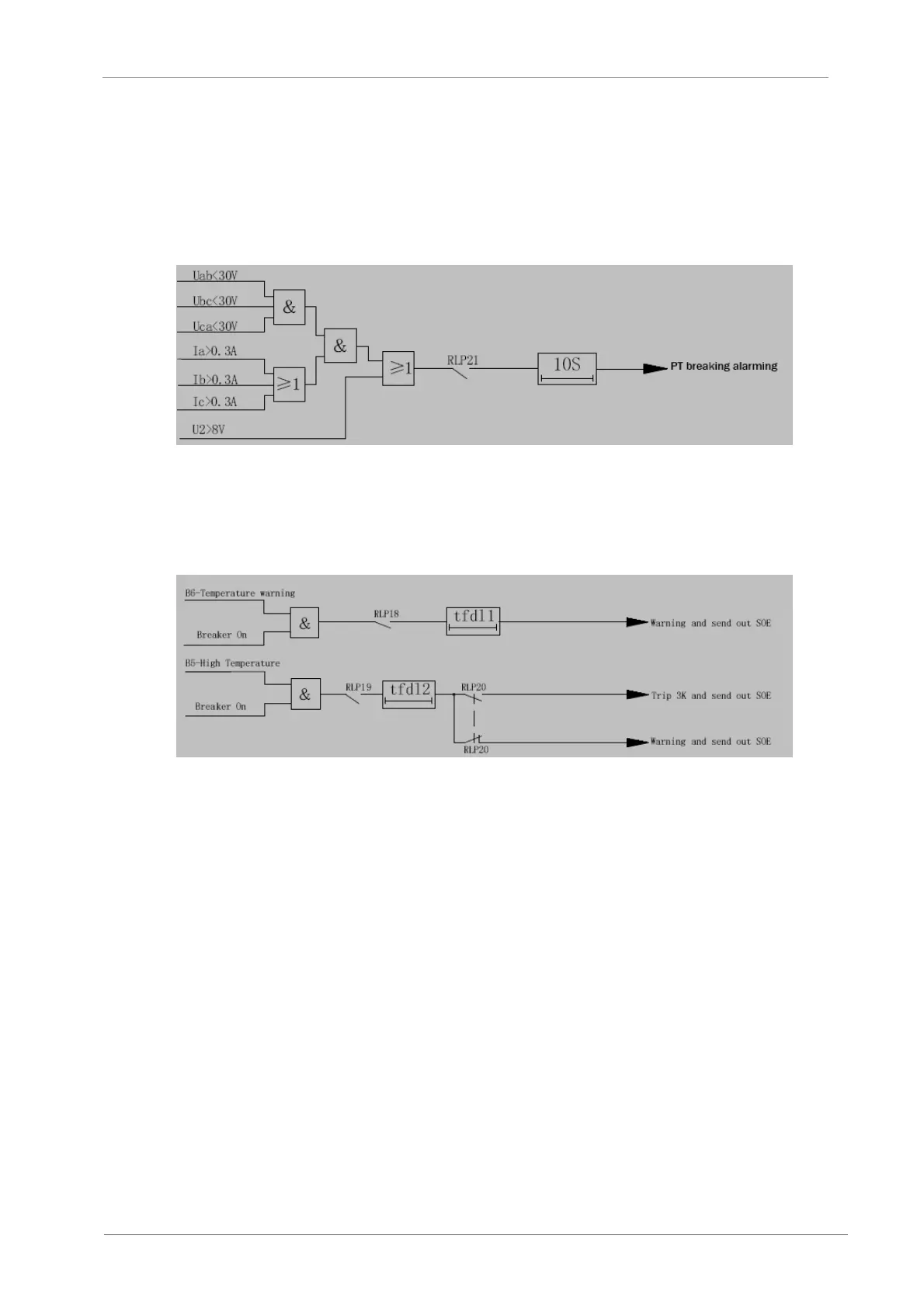
PT breaking protection
The device can detect the PT breaking status. If meet any conditions as below, the device will
send out the warning signal after 10 seconds.
a) The max. phase voltage is less than 30V and any phase current is larger than 0.3 A
b) The negative sequence voltage is larger than 8V.
Figure 8.12 Logic diagram of PT breaking protection
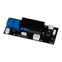
Non-electric protection
The device can provide two ways of non-electric protection including temperature rising warning
and high temperature trip or warn.
Figure 8.12 Logic diagram of Non-electric protection
Warning function
Control loop breaking: checking the trip loop while the breaker is ON, and checking the close loop
while the breaker is OFF.
Abnormal status: detecting power loss or self-diagnose error (ROM, RAM, EPROM, etc.)
Measurement
Frequency: f
Voltage: Uab, Ubc, Uca, Ua, Ub, Uc, Uzero
Current: Ia, Ib, Ic, Izero
Power: Active power, reactive power, power factor
Control
You can operate the breaker to trip or close at the remote control or at the manual operation by
the keypad. The interval between two operations must be longer than 10 seconds.