www.powerbox-systems.com
27
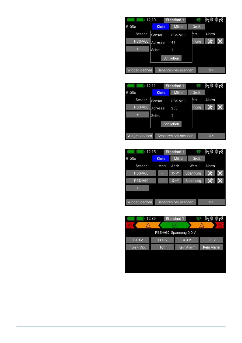
A long press on the sensor name now displays the
current address. This is purely for information pur-
poses - address management is carried out auto-
matically by the CORE.
Press the X->Y button in order to change the ad-
dress. Another long press on the sensor name will
show you that the address is now different from the
previous one:
The next sensor can now be connected. Repeat the
procedure outlined above if you wish to connect more
sensors. Proceed as before if several sensors of the
same type are to be connected.
- Telemetry alarms
Behind the individual sensor values you will nd the
Alarm button. The Alarm menu allows you to set
four alarm thresholds: one yellow alarm and one red
alarm for each direction. This enables you to select
different thresholds coupled to different sounds,
text, or vibration modes.
For example, you might set up battery capacity
alarms for an electric model: a yellow audible alarm
when there
is just sufcient energy remaining for one minute of
ight; a red audible alarm with vibration for 20 se-
conds.
Pressing the Back button returns you to the sensor overview. The last button (cross symbol) is used to delete
individual telemetry values from the widget.
Press OK at the bottom once you have completed all your settings.