Squaring Miter Gauge (model PM2000BT):
1. Place a square against miter gauge face, and
against flat of blade. (Place square against flat
of blade, not against the teeth which are set
wider than the blade body).
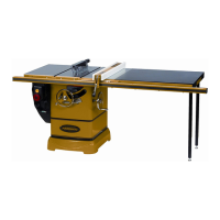
2. Loosen screws A and B as shown in Figure 8-
3C.
3. Adjust the miter gauge fence to make it square
to the blade. Tighten screws A and B.
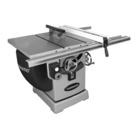
4. After squaring, if the red pointer (C) is not
pointing at 0°, loosen the pointer setscrew (see
Figure 8-3B), rotate the pointer to 0°, and re-
tighten the pointer setscrew.
Figure 8-3B
Adjusting Miter Gauge Angle for
Operations
(model PM2000BT, refer to
Figure 8-3C)
:
1. Unscrew handle (D) just enough to loosen it.
2. Press black tab (E) to release it from stop 0°.
3. Rotate gauge body until red pointer (C) lines up
with desired angle on scale.
4. Tighten handle (D).
5. There are 13 stops at 0°, 15°, 22.5°, 30°, 45°,
60°, and 67.5° left and right. Each of these can
be adjusted to by allowing the spring stop to
lock into each location. Press black tab (E) to
move past each stop location.
Figure 8-3C
8.6 Blade Tilt Stop Adjustment
The stops for 90°, 45° blade tilt, and elevation
settings have all been factory set, and should
require no immediate adjustment. The settings
should be confirmed by the operator, however, and
especially if cuts become inaccurate. Both tilt stops
are located on the trunnion.
8.6.1 Tilt Stop 90°
1. Disconnect machine from power source.
2. Make sure table insert has been leveled with
table surface (sect. 6.8).
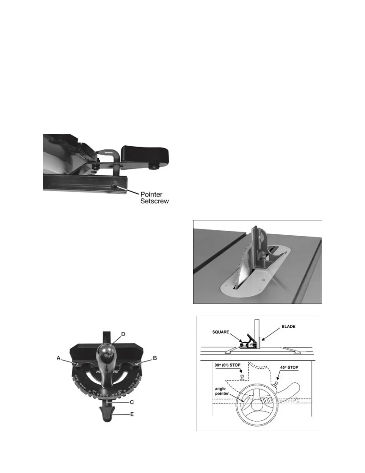
3. Raise blade to highest position and place a
square on table and against blade (Figure 8-4).
Make sure that a blade tooth does not obstruct
the actual reading.
4. Tilt blade with handwheel until square and
blade are flush.
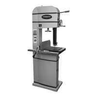
5. If adjustment is required, loosen nut on 90° stop
screw (Figure 8-5) with 13mm wrench, and turn
screw to proper height. Verify setting and
retighten nut against trunnion.
6. Check pointer position on scale (Figure 8-5). If
needed, loosen screw and adjust pointer to
zero. Retighten screw.
Figure 8-4
Figure 8-5: blade stops