2 INSTALLATION AND SETUP continued
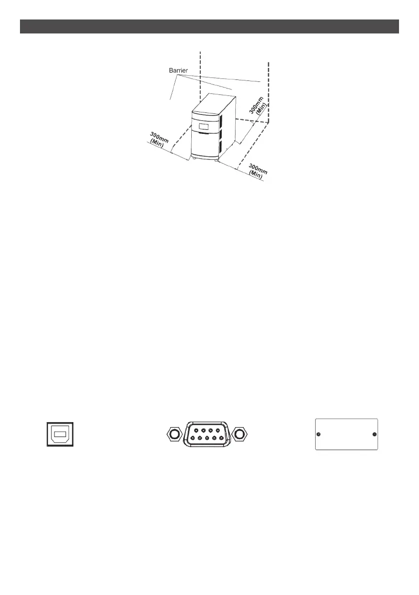
Place the UPS in a well-ventilated area. It is required to maintain a minimum clearance of
100mm in the front of the UPS and 300mm in the back and two sides of the UPS for heat
dissipation.
Maintain an ambient temperature range of 0ºC to 40ºC for UPS optimal operation.
Step 1: UPS input connection
Plug the UPS into a two-pole, three-wire, grounded receptacle only. Avoid using extension
cords.
Step 2: UPS output connection
There two kinds of outputs: programmable outlets (white coloured outlets) and
general outlets (black coloured outlets).
During power failure, you may extend the backup time by turning off the white coloured
outlets before the general outlets.
Step 3: Communication connection Interface ports:
To allow for unattended UPS shutdown/start-up and status monitoring, connect
the communication cable at one end to the USB/RS-232 port and the other to the
communication port of your PC. With the monitoring software installed, you can schedule
UPS shutdown/start-up and monitor UPS status through PC.
The Commander series are equipped with an intelligent slot for either SNMP, AS400 or
MODbus cards.
USB Port RS-232 port
Intelligent slot
9