36
Powerware 9315 (200 kVA---300 kVA) Operation
164201036 Rev. D 041500
Relay Interface Module
An optional Relay Interface Module (RIM) uses relay contact closures to indicate
the operating status and alarm condition of the UPS system. A maximum of two
monitoring accessories (RMPs, RIMs, or SCMs) can be installed. See Table 1 for
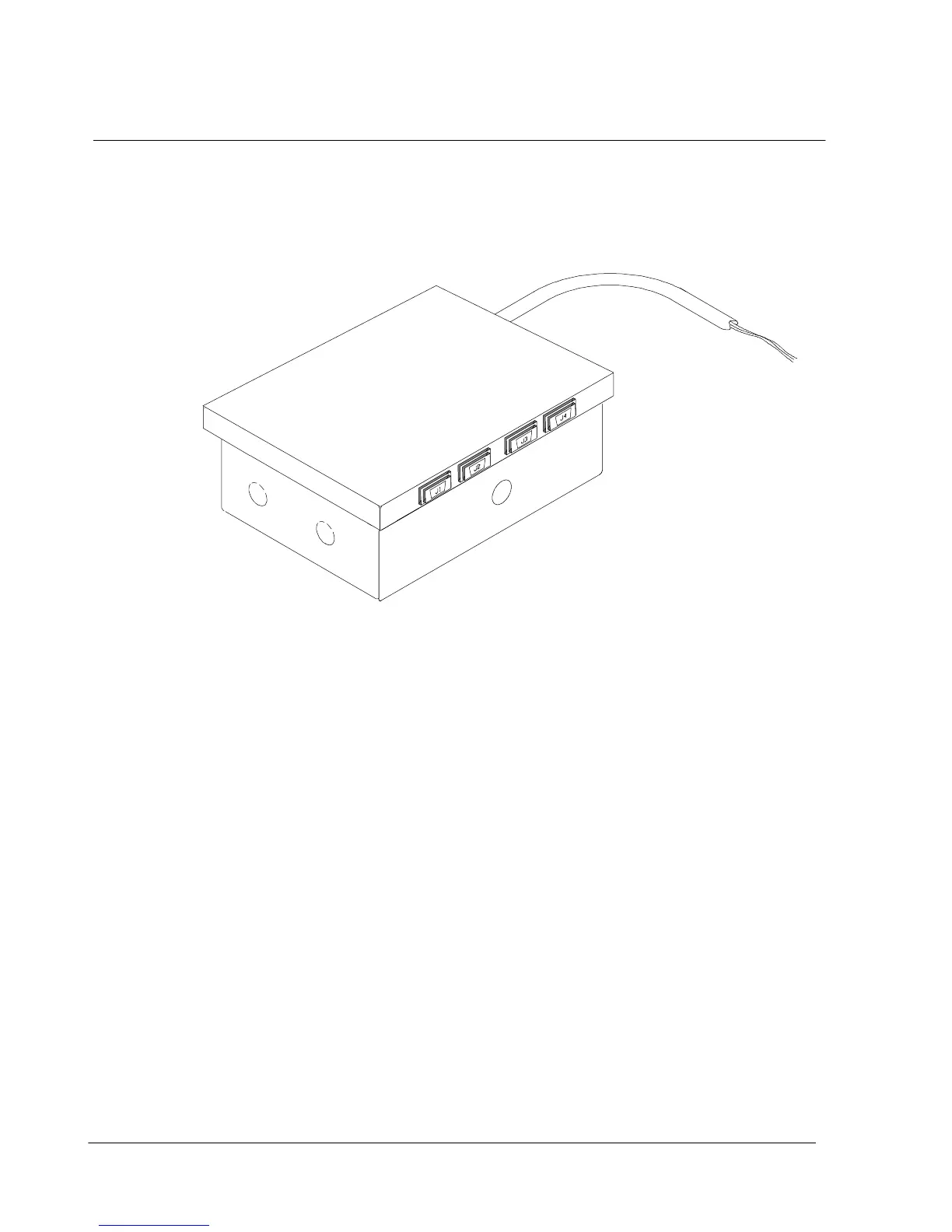
the number of accessories permitted. Figure 21 shows the RIM with its four 15-pin
connectors labeled J1 through J4.
Figure 21. Relay Interface Module
TheRIMcanprovidethesesignals:
· UPS AVAILABLE (pins 1 and 12) Contacts are closed when the UPS is
offline.
· UPS OFF LINE (pins 3 and 13) Contacts are closed when the UPS is
operating in Normal mode.
· UTILITY FAILURE (pins 6 and 15) Contacts are closed when Utility Failure is
detected.
· BATTERY WEAK (pins 5 and 14) Contacts are closed when approximately
2 minutes of battery time is remaining, before the critical
load is lost.