37
Powerware 9315 (200 kVA---300 kVA) Operation
164201036 Rev. D 041500
Supervisory Contact Module
An optional Supervisory Contact Module (SCM) establishes an interface between
the UPS manufacturer’s equipment and the customer’s monitor. This interface
allows the customer to monitor operational status of the UPS equipment. A
maximum of two monitoring accessories (RMPs, RIMs, or S CMs) can be installed.
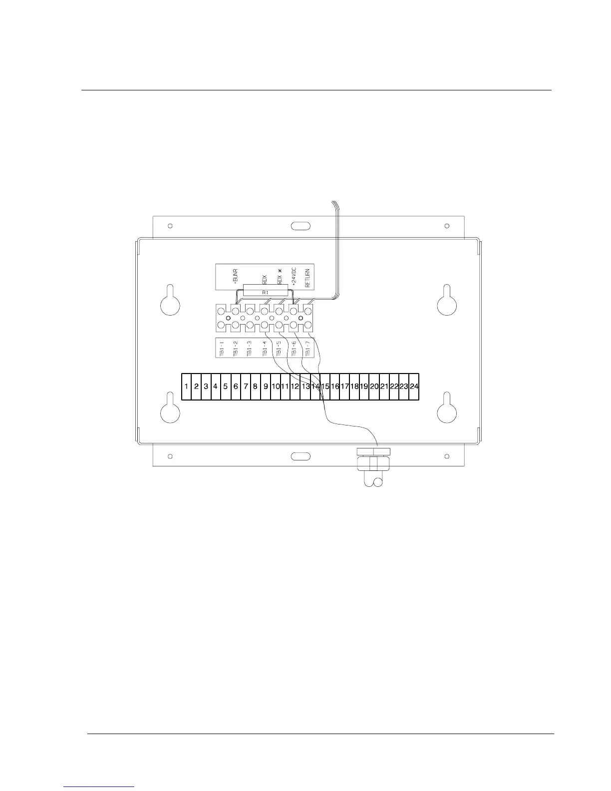
See Table 1 for the number of accessories permitted. Figure 22 shows the SCM,
input connections on TB1, and output connections on TB2.
TB2
Figure 22. Supervisory Contact Module
The SCM provides signals for the following indications:
· SYSTEM NORMAL T B 2 --- 1 t h r o u g h T B 2 --- 3
· NO REDUNDANCY T B 2 --- 4 t h r o u g h T B 2 --- 6
· ON GENERA TOR T B 2 --- 7 t h r o u g h T B 2 --- 9
· BYPASS NOT AVAILABLE T B 2 --- 1 0 t h ro u gh T B 2 --- 1 2
· ON BATTERY T B 2 --- 1 3 t hr o u gh T B2 --- 1 5
· UPS ALARM T B 2 --- 1 6 t hr o u gh T B2 --- 1 8
· ON BYPASS T B 2 --- 1 9 t hr o u gh T B2 --- 2 1
· SHUTDOWN IMMINENT TB 2 --- 22 t h r o u g h TB 2 --- 2 4
Refer to P owerware Plus Installation manual, Chapter 12, for TB2 contact
configurations.