Installation
33
Powerware
®
PrestigeSeriesInstallationand Operator’s ManualforIBM Applications (6000 VA)Uncontrolled Copy
NOTE You caninstalladditionalbatterycabinetswhile the UPS isoperating,but
confirm theUPSisnot inBattery mode (seepage 47).
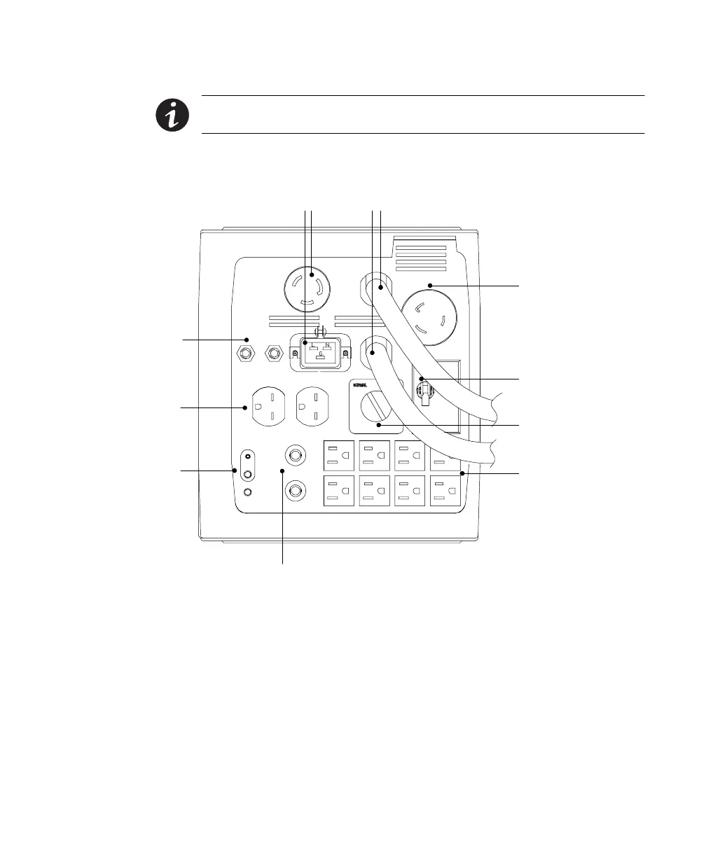
2. Verify the Bypass switch on the PPDM rear panel is in the
NORMAL position.
Utility Input
(L6-30R) To
PowerPass
(Cord Provided)
Input Breaker
Bypass Switch
5-15R
Receptacles
L6-30R and IEC 320-C19 Receptacles
5-15R Circuit Protectors
Power Cords To PPU
Circuit Protectors
6-15R Receptacles
Neutral Ground
Screw
Figure 5. L6-30R/IEC 320-C19 PPDM Rear Panel Connections
3. For L6-30R/IEC 320-C19 PPDMModels Only: The factory default for
the PPDM output neutral is grounded. In some countries, the
output neutral should not be grounded. If your application
requires an ungrounded output neutral, continue with Step 3;
otherwise, skip to Step 4.
For ungrounded output neutral applications only. Remove the
ground screw, rotate the ground cover until it snaps into place,
and reinstall the ground screw in the ungrounded position (see
Figure 6).