• The output current is enabled / disabled by a digital controlling signal. Please
note that the output current is disconnected until +Vsupply is applied to termi-
nal 3.
Input:
• Programmable current or voltage input for standard signals acc. to order
schedule, joystick / potentiometer or a special non-programmable input.
• Digital inputs for external control functions.
Output:
• A pulsating current output prevents the connected valve from sticking.
• Optional programming of the modulation frequency (PWM) between 8 and 400 Hz.
• The internal measuring and control circuit ensures that the mean current never
exceeds the entered Ivalve.
• If the peak current ex ceeds 7 A the output will be disabled.
23
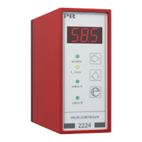
VALVE CONTROLLER 2224
• Front-programmable
• mA, V, and Ω-programmable input
• Ramp times, jump values, reversal, chopper frequency,
and deadband
• 3-digit LED display shows Ivalve % value
• 1 or 2 channels
• Modulated current output for proportional valve
Applications:
• Control and regulation of single or double-coil hydraulic and pneumatic pro-
portional valves.
• The unit is used for accurate oil flow regulation, linear soft acceleration and
deceleration, modulated output signal, and programmable deadband.
• Is highly suitable for joystick regulation of A/B movements.
Technical characteristics:
• The 2224 Valve Controller is a microprocessor-based unit containing ramp
functions for soft start and stop and jump functions thus avoiding deadband
at start and changes between A & B valves.
• The user interface of the valve controller consists of three pushbuttons and a
3-digit LED display. By using these, output currents, ramp times, jump values,
chopper frequency, reversal, deadband, and on/off functions are changed.
• During operation the display shows the present output signal as a % of the
Ivalve.
• All parameters are protected against unauthorised changes with a password.
• Changes between A and B valves can be made in two ways. By way of function
1, the A valve is chosen when +Vsupply is applied to terminal 2. By way of
function 2, changes between A/B valves take place automatically according
to the value of the input signal (no signal on terminal 2).
22