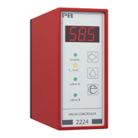
TECHNICAL DESCRIPTION
• To prevent programming during operation, two safety measures have been
included: The correct password (030) must be entered in menu [PAS], and
the output must give no signal (000 must be displayed). This is achieved by
disconnecting +Vsupply on terminal 3.
• The 2224 Valve Controller can be controlled by a joystick / potentiometer
using the internal +10 V and -10 V supply, or a process current / voltage sig-
nal. For process signals the differential amplifier (DP1 switch 6 off) will reduce
disturbances from noisy signals. Joysticks / potentiometers are connected
single-ended (grounded), and it is possible to connect a 10 kΩ load resistor
(DP1 switch 5 on), providing a minimum potentiometer load current.
• A switch between A and B valves can be made in two ways. By way of
function 1, the A valve is chosen when +Vsupply is applied to terminal 2.
By way of function 2, changes between A/B valves are made automatically
according to the value of the input signal (no signal on terminal 2). Input:
0...50% = A valve 100...0%. Input: 50...100% = B valve 0...100%.
• When connecting the output to a solenoid please ensure that the peak
valve current = V
supply
/ R
solenoid
does not exceed 7A.
• A deadband can be programmed to avoid unintentional activation of the
valve in connection with e.g. an inaccurate neutral position of joysticks. The
deadband introduces a threshold which must be exceeded before any output
activity will take place.
• The spring response (bias) can be adjusted to account for the valve seat
travel before oil flow.
• Two current limits can be programmed (Imax1 & Imax2) for limit stop detection
featuring slow motion before stop. The active current limit (Imax1 & Imax2) is
selected by the PNP input signal on terminal 7.
• The 2224 Valve Controller complies with EMC data only when shielded
cabling is used and the shield is connected to supply ground.
31
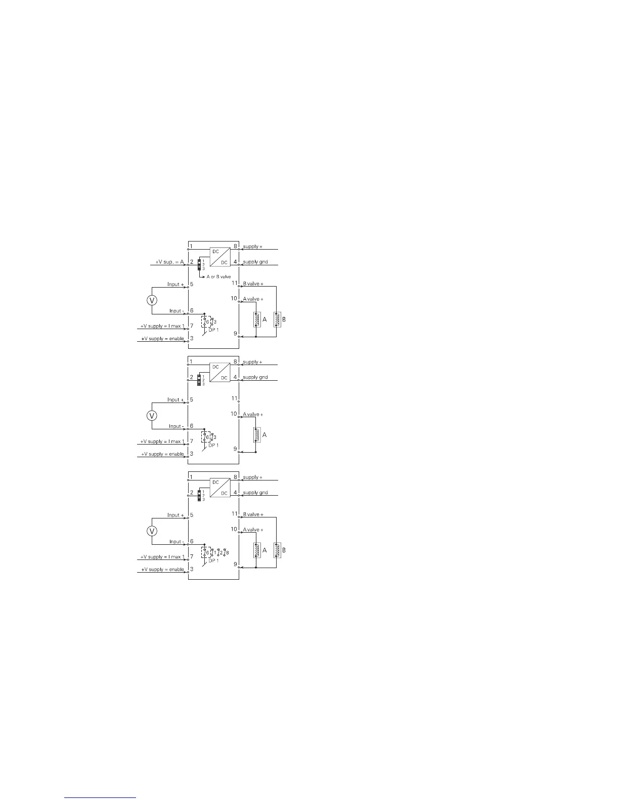
WIRING DIAGRAMS FOR
DC VOLTAGE INPUT
Double valve control (A/B
valves) from a 0...1 VDC
input signal.
DIP-switch programming:
Function 1 or
Function 2.
Single valve control from
a 0...1 VDC input signal.
DIP-switch programming:
Function 1.
Double valve control (A/B
valves) from a -10...+10
VDC input signal.
DIP-switch programming:
Function 1 or
Function 2.
30