27
DP 1 DP 1
DP 1
DP 1 DP 1
DP 1
DP 1 DP 1
DP 1
DP 1 DP 1
DP 1 DP 1
DP 1
DP 1 DP 1
**
*
**
*
**
*
*
()
*
()
*
()
*
*
*
On
Off
On
Off
On
Off
On
Off
On
Off
On
Off
On
Off
On
Off
On
Off
On
Off
On
Off
On
Off
On
Off
On
Off
On
Off
On
Off
12
3
45678 12
3
45678
12
3
45678
12
3
45678 12
3
45678
12
3
45678
12
3
45678 12
3
45678
12
3
45678
12
3
45678 12
3
45678
12
3
45678 12
3
45678
12
3
45678
12
3
45678 12
3
45678
2 - 3
2 - 3
2 - 3
2 - 3
2 - 3
2 - 3
2 - 3
2 - 3
1 - 2
- - - -
0...10 V
-10...+10 V
No function
No function
No function
No function
Function
1:
Function
2:
Signal
input:
Joystick / potentiometer via
internal reference voltage
Input: Grounded Differential
JP1
pos.:
0...20 mA
4...20 mA
0...1 V
0.2...1 V
0...10 V
2...10 V
-10...+10 V
TIMING DIAGRAM
DIP-switch programming:
Input signal and function are chosen via the DIP-switch setting.
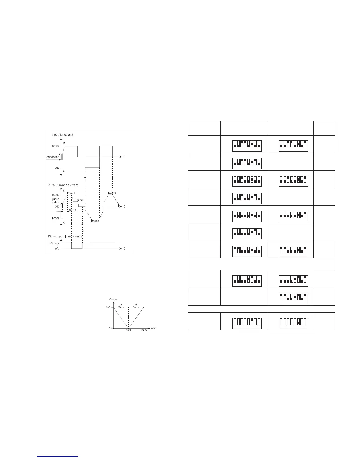
Function 1:
Single and double valve control. By double valve control, A valve is chosen by
applying +Vsupply to terminal 2.
Function 2:
Double valve control with automatic change between A and B valves (no signal
on terminal 2).
Input: 0...50% = A valve 100...0%.
Input: 50...100% = B valve 0...100%.
26