www.predig.com
Overview
The following field wiring connections are made to removable screw
terminal blocks supplied with the meter:
Power, Signal Input, Acknowledge and Hold
Options: Relays & 4-20 mA Output
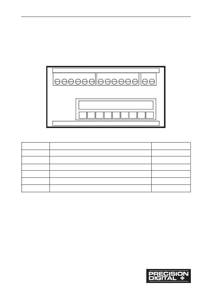
Figure 1: Rear View of Meter (Connectors)
Wiring Instructions
1. All field connections to be made with either solid or stranded
insulated wire. Strip length =
1
/4" (7 mm). Tighten all screw
terminals to 4.5 lb-in (0.5 Nm). Do not pre-treat wire with solder.
2. Terminals connected to line voltage (e.g. L, RELAY 1-4): Use AWG
# 12-18 copper wire, 600 volt, 60°C or 60/75°C. Connect only one
wire to each terminal.
3. Terminals not connected to line voltage (e.g. AK, H, CM, S+, S-, P+,
P-, V+, V-, OUTPUT): Use AWG #12-22 wire. If using AWG #20 or
smaller wire, up to two wires may be connected to each terminal.
If using AWG #18 or larger wire, only one wire
may be connected to each terminal.
Model PD690 Universal Process Meter Instruction Manual
11
Label Main Board (Lower) Wire Size
None Power 12-18
None Signal, Acknowledge, Hold 12-22
Options Board (Upper)
J1 4-20 mA Output 12-22
J2 Relays 1 & 2; NC, NO, Common 12-22
J3 Relays 3 & 4; NC, NO, Common 12-22
 Loading...