EasyManuals Logo

Precision Digital Corporation PD690 Series User Manual

Precision Digital Corporation PD690 Series
36 pages
To Next Page IconTo Next Page
To Previous Page IconTo Previous Page
Page #15 background imageLoading...
Page #15 background image
www.predig.com
Model PD690 Universal Process Meter Instruction Manual
Relays & 4-20 mA Output
Depending on the model number, the Options Board may contain two
or four relays and an Isolated 4-20 mA Transmitter Output. Relay con-
nections are made to removable screw terminal connectors located at
J2 and J3 on the Options Board. Connections for the Isolated 4-20 mA
Transmitter Output are made to J1 on the Options Board.
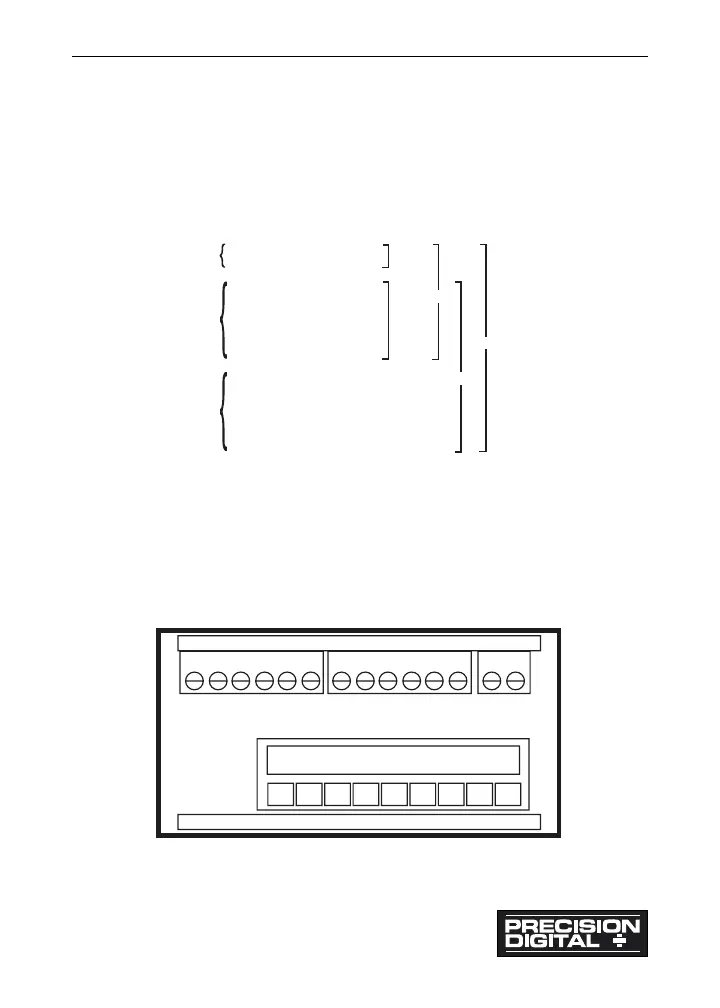
Figure 8: Option Card Pinouts
Notes:
1. Alarm acknowledgement terminals (ACK and COM) are located on
the meter main board.
2. In the alarm condition, the NC contact is connected to common in
the fail safe mode.
Figure 9: Rear View of Meter (Connectors)
15
Relay #1 Common
Relay #1 NC
Relay #1 NO
Relay #2 Common
Relay #2 NC
Relay #2 NO
Relay #3 Common
Relay #3 NC
Relay #3 NO
Relay #4 Common
Relay #4 NC
Relay #4 NO
Fu nction:
Transmitter +
Transmitter -
Pi n:
1
2
3
4
5
6
1
2
1
2
3
4
5
6
PD175
PD178
PD177
PD176
PD174
J1
J2
J3
A
K
H S S P P L L
+
+
-
-
-
+
J3 J2 J1
6 5 4 3 2 1 6 5 4 3 2 1
CM

Table of Contents

Questions and Answers:

Question and Answer IconNeed help?

Do you have a question about the Precision Digital Corporation PD690 Series and is the answer not in the manual?

Precision Digital Corporation PD690 Series Specifications

General IconGeneral
BrandPrecision Digital Corporation
ModelPD690 Series
CategoryMeasuring Instruments
LanguageEnglish

Related product manuals