www.predig.com
Lockout Jumper
Once the meter has been completely programmed, a lockout jumper
can be installed to restrict further modification to the meter. This
jumper is located at the rear of the instrument and is labeled J3.
When ENTER is pushed with the lockout jumper in place, only ALArS
and ovtPvt routines are displayed. These routines may be entered to
view their settings, but the settings may not be altered.
SWITCHING INDUCTIVE LOADS
The meter has the ability to suppress electrical noise generated by
switching inductive loads. However, installing Resistor Capacitor (RC)
Networks improves this performance and prolongs the life of the
meter's relay contacts. This suppression can be obtained with RC
networks assembled by the user or purchased as a complete assembly.
Refer to the following circuits for RC network assembly and installation:
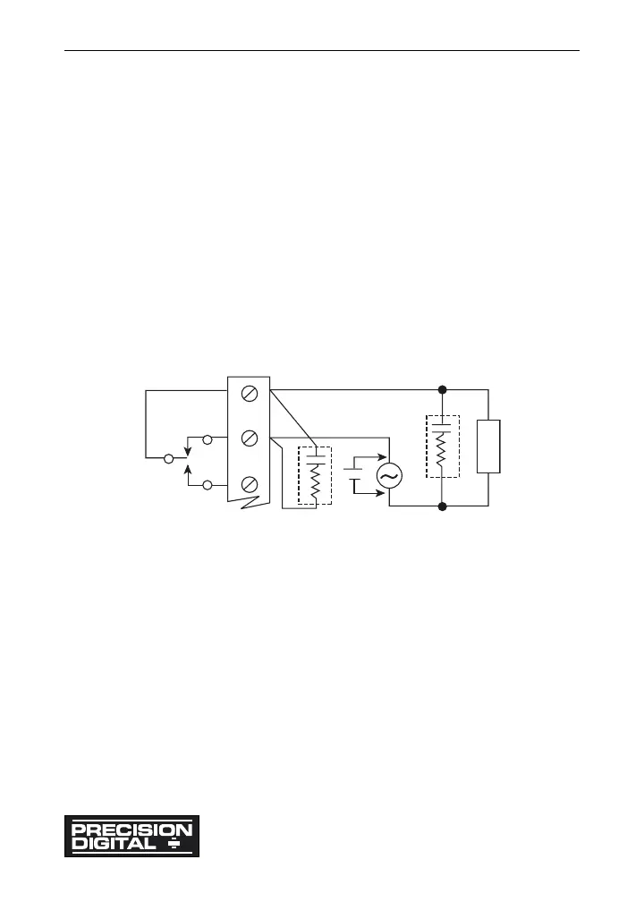
AC & DC Loads
Figure 15: AC & DC Loads
Choose R and C as follows:
R: 0.5 to 1 ! for each volt across the contacts
C: 0.5 to 1 µF for each 1 A through closed contacts
Notes:
1. Use capacitors rated for 240 VAC.
2. Snubbers may affect load release time of solenoid loads, check to
confirm proper operation.
3. Install the RC network right at the meter's relay screw terminals. An RC
network may also be installed across the load.
Model PD690 Universal Process Meter Instruction Manual
30
 Loading...