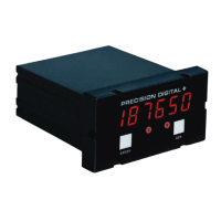
Model PD690 Universal Process Meter Instruction Manual
SPECIFICATIONS
Except where noted all specifications apply to operation at +25ºC
Basic Meter
INPUTS Field selectable:
4-20 mA, 0-20 mA, 0-5 V, 1-5 V, 0-10 V.
DISPLAY Bright, large, 0.56" (14.2mm) high efficiency
red LEDs. 4
1
/2 digits + extra zero may be
switched on to display +/- 19,999(0). Leading
zeros blanked.
DECIMAL POINT Decimal point may be placed in any of the
following positions. 1.9999, 19.999,199.99,
1999.9, 19999 or 199990 with extra zero.
CALIBRATION 4 mA (1 V) input may be set anywhere in range
RANGE of the meter. 20 mA (5 V) may be set anywhere
in range of the meter above or below 4 mA
input. An Error message will appear if Input 1
signal and Input 2 signal are too close together.
Input Minimum Difference Between
Range: Input 1 & Input 2:
0-5 V 0.16 V
0-10 V 0.32 V
4-20 mA 1.60 mA
INPUT Voltage ranges, greater than 300 KΩ;
IMPEDANCE current ranges, 100-120 Ω.
LOOP POWER
(AC powered meters only), Isolated 24 VDC ± 5%
@ 20 mA regulated. Maximum loop resistance
is 1200 Ω. Available for either signal input or
4-20 mA output, but not both.
HOLD READING Connect terminals H and CM
ACCURACY ±0.05% of calibrated span, ±1 count.
SQUARE ROOT ±0.1% F.S. ± 1 count from 10-100% of flow.
EXTRACTION
LOW FLOW Any input below the Low-Flow Cutoff point will
CUTOFF result in a display of zero.
May be set from 1
count to 100% of full scale, user selectable.
6
www.predig.com
 Loading...