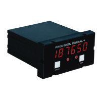
Model PD690 Universal Process Meter Instruction Manual
RESET User Select:
1. Automatically when input passes reset point.
2. Automatically + Manually (via user supplied
switch or front panel ACK button). Manual
reset resets all manually resetable relays.
DEADBAND 0-100% of full scale, user selectable.
HIGH OR LOW User may program any alarm for a high or low
ALARM trip point.
FAIL-SAFE Relay coils are energized in non-alarm
OPERATION condition. In case of power failure, relays will
go to alarm state. Fail-Safe operation may be
disabled, by removing jumper J2 located on the
Options Board.
AUTO When power is applied to the meter, relays will
INITIALIZATION
always reflect the state of the input to the meter.
Isolated 4-20 mA Transmitter Output
CALIBRATION The transmitter output can be calibrated so that
RANGE a 4 mA output is produced for any number
displayed by the meter. The 20 mA output may
correspond to any number that is at least 501
counts greater or smaller than the number
corresponding to 4 mA. (Ex. 4 mA = 0, 20 mA =
501) If the span between 4 and 20 mA is less
than 501 counts, an error message will appear.
EQUIPMENT The 4-20 mA output is calibrated without
NEEDED the use of a calibrator. No equipment needed.
OUTPUT
(AC powered meters only), Isolated 24 VDC ± 5%
LOOP-POWER @ 20 mA regulated. Maximum loop resistance
is 1200 Ω. Available for either signal input or
4-20 mA output, but not both.
ACCURACY ± 0.1% F.S., ± 0.004 mA.
ISOLATION 500 VDC or peak AC, input-to-output or
input/output-to-power line.
EXTERNAL LOOP- 35 VDC max.
POWER SUPPLY
OUTPUT LOOP Power supply Min. loop Max loop
RESISTANCE resistance resistance
24 VDC 10 ! 600 !
35 VDC (external) 600 ! 1000 !
8
www.predig.com

 Loading...