page 12
COMMERCIAL PRODUCTS DIVISION
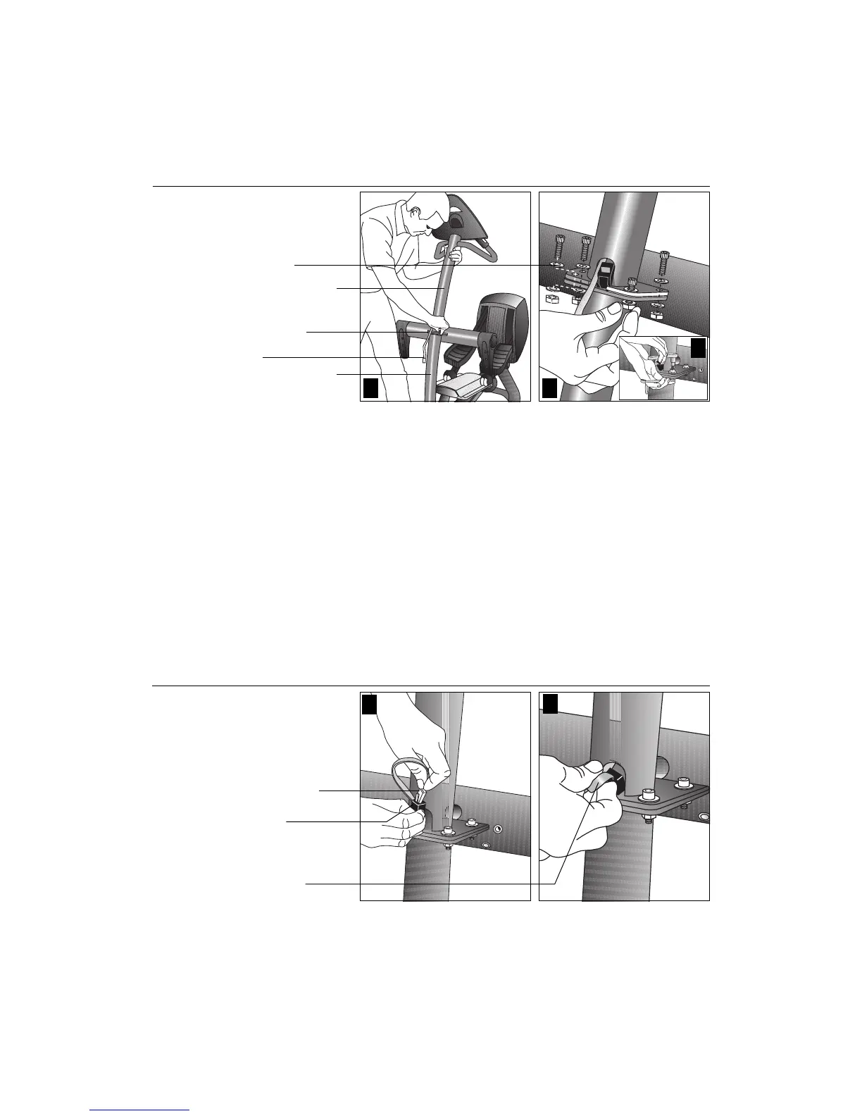
3. Attach the upper assembly. Diagram 4. Have an assistant hold the upright
support over the base frame bracket, while you take the following steps:
a. Remove any tape (or wire ties) that fasten the cables to the base assembly.
Ensure that the cables are out of the way while your assistant aligns the
upright support to the base frame bracket mounts.
b. Place a washer (B) on each of four stainless steel socket head screws (A) and
insert the screws through the mounting holes. Place a washer (B) and thread a
hex nut (C) onto each screw. See Diagram 4, #2. Wrench tighten using a ¹⁄₄-inch
hex key and ¹⁄₂-inch open- or box-end wrench. See Diagram 4, #3.
CAUTION: Do not stretch, crimp, or damage the cable. Excess cable may be
gently pushed into the upper support tube. Cables damaged by improper
installation will not be covered by the Precor Limited Warranty.
Diagram 4
1 2
4. Connect the cable. Diagram 5. Insert the cable into its receptacle. Just like a
telephone connection, a definite "click" is heard when a good connection is
made. If you do not hear a "click," try reinserting the cable again. Place the
excess cable inside the upper portion of the support tube.
Important: Recheck that the cable connection is secure after you push the
excess cable inside the support tube.
Diagram 5
Connect the cable.
Base frame support
Upper support tube
1
2
Screws (A) and
washers (B)
Cable
Lower bracket
3
Secure the console
assembly to the
base frame.
Cable connector
Cable
receptacle
Push excess cable
inside upper
support tube.