12
System Installation
ContrContr
ContrContr
Contr
ol Boarol Boar
ol Boarol Boar
ol Boar
d d
d d
d
TT
TT
T
erer
erer
er
minal Charminal Char
minal Charminal Char
minal Char
t (#28-107)t (#28-107)
t (#28-107)t (#28-107)
t (#28-107)
I/O BoarI/O Boar
I/O BoarI/O Boar
I/O Boar
d d
d d
d
TT
TT
T
erer
erer
er
minal Charminal Char
minal Charminal Char
minal Char
t (#28-108)t (#28-108)
t (#28-108)t (#28-108)
t (#28-108)
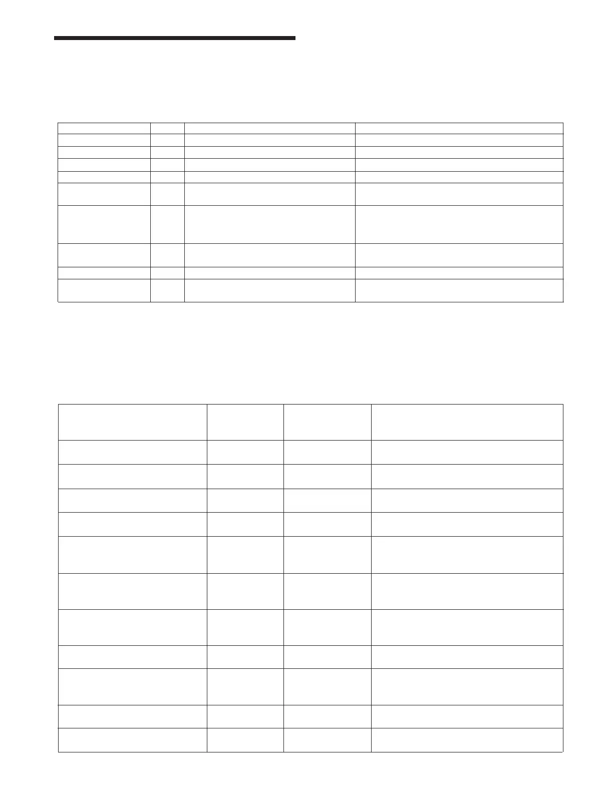
Resolver J11 Connection to resolver See Resolver #28-100 for details
RS-232 J8 Standard serial port interface Standard DB-9 female port
RS-485 J12 Optional interface Half duplex
LCD J14 Connection to LCD
LCD invertor J3 Connection to LCD backlight
KNOB J2 Connection to encoder KNOB
and pushbutton
KEY J6 Connection to key switch Pin 1 = ground
Pin 2 = key input
Pin 3&4 = optional inputs
Power Input J1 +24vdc unregulated input Pin 1&2 = +24vdc
Pin 4&5 = ground
I/O connection P1 I/O connection to I/O board
Software update J4 Jumpers allow in field software Consult factory on procedure.
mode upgrades
Output #1-11(form C) J1-J3 Limit Switch 1 -11 Up to 3 output windows based on crank
angle. LS 8-11 can be timer based if
desired.
Output #12(form C) J3 Counter Opens when Batch counter incremented,
or Quality Count reached.
Output #13(form C) J10 Die Fault Remains closed in PROG mode. Opens in
RUN mode when Die fault occurs.
Output #14(N.O.) J12 Speed Closes when press speed falls with the
Min and Max speed setpoints.
Output #15 & #16(N.O.) J14-J16 General Faults Opens when any fault occurs, except
when a Die fault occurs in PROG mode.
Inputs #1-12 J13 Die Sensor signals Signal sent back from sensors using a
(with their own common term.) (Input #7 is simple contact closer. One side of sensor
(12Vdc standard) parts counter) is grounded, the other side is the signal.
Inputs #13-16 J11 Die Sensor signals
(with their own common term.)
(12Vdc standard)
Input #17 (120Vac standard) J15 Brake/Clutch signalParallel signal sent by the press control
going to the valves.Voltage = press
movement.
+24Vdc unregulated J9 Power Out to Pin 1&2 = +24vdc
Control board Pin 4&5 = ground
+12Vdc regulated J6 Output for Die Connect the + to the Die Sensor common
Sensors only terminals and the - to the grounded side of
the Die Sensors.
Power Input (120Vac standard) J7 Power input for Supply Line, Neutral, Ground
entire system
I/O connection P1 I/O connection to
control board