39
Tonnage Load Monitor (optional)
Installation
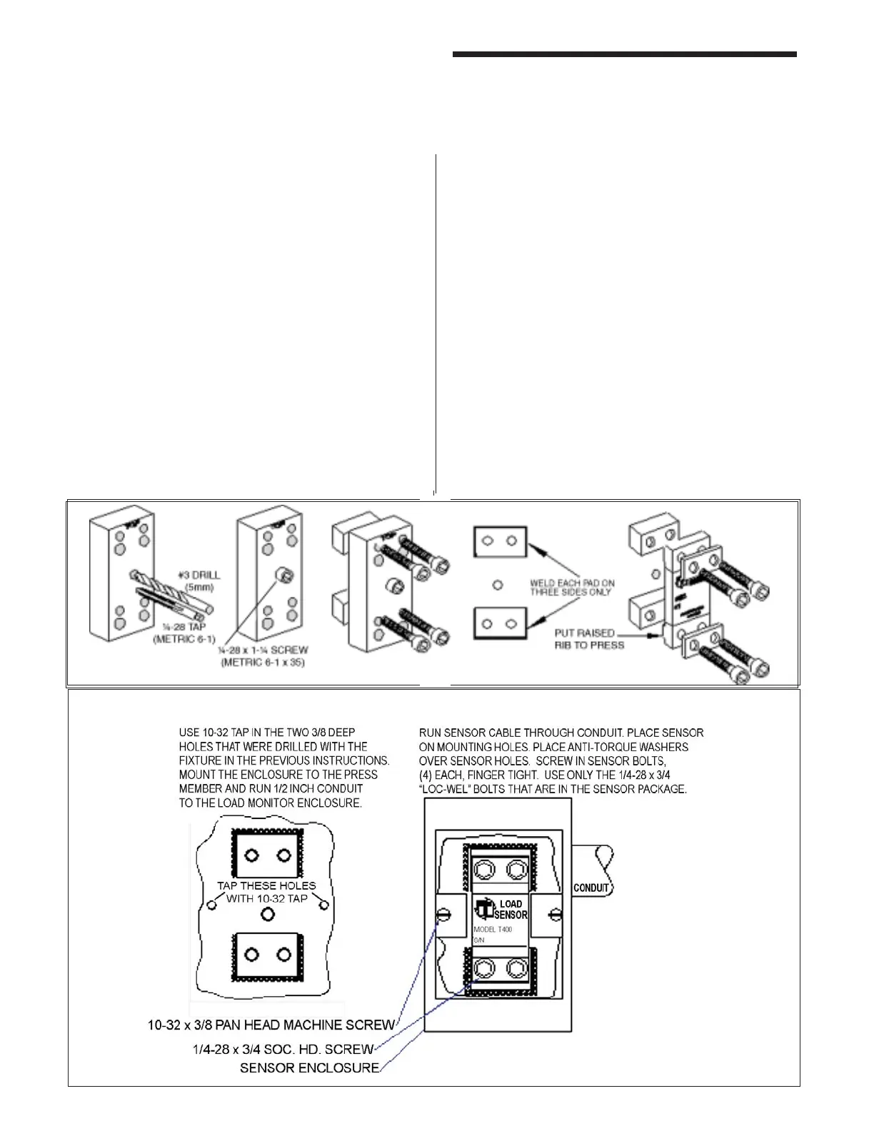
SENSOR ENCLOSURE MOUNTING
Using the T400 Sensor Installation
Fixture Kit No. 1977
Weld Pad Method for Mounting Sensors
Step No. 1 Remove all paint, grease, or rust from
surface to be welded (surface should be
fl at T.I.R. 1/32 of an inch).
Step No. 2 Bolt the weld pads to the fi xture with the
socket head cap screws provided. The
user may want to drill and tap for the
center holding screw. The center hole
may be used to hold the fi xture down fl at
and tight while welding the weld pads to
the press member.
Step No. 3 Hold the fi xture fl at and tight. Weld the
weld pads to the press member. Be
sure to only weld the weld pads on
three sides, as shown. A single pass is
suffi cient. Do not remove fi xture until slag
is removed and or assembly has cooled.
The four screws may be discarded. Do
not use screws to assemble sensor.
When welding to cast iron, use a dry
nickel rod such as: Lincoln Electric “Soft
Weld” Hobart “NI Cast 99” MB Weld
Prod. “MG 210” Strike arc on steel then
puddle into the cast iron.
Step No. 4 Remove weld fixture. Do not weld
after fixture is removed. Weld Pad
surface must be clean - no weld bumps,
scratches, etc. Be sure tapped holes
are clean and bottom of holes are free
of weld fl ash.
Step No. 5 Mount the sensor with raised rib to the
press. The anti-torque washers should
go between the screw and the sensor
body.