38
Using the T400 Sensor Installation
Fixture Kit No. 1977-749
(Metric Installation Fixture Kit No. 1974-749)
Drill and Tap Method for Mounting Sensors
Step No. 1 Paint must be sanded off and or grease
removed from sensor mount area. If the
machine surface is fl at (total indicated
reading of .002”) and smooth (125 μ in.)
the load sensor can be bolted directly
to the surface.
Step No. 2 Drill and tap the center hole for mounting
the fi xture to the press member. This
hole should be 1/2 of an inch deep. Be
sure the sensor location follows the
best location described on the print.
(Drawing Numbers 3021, 4557).
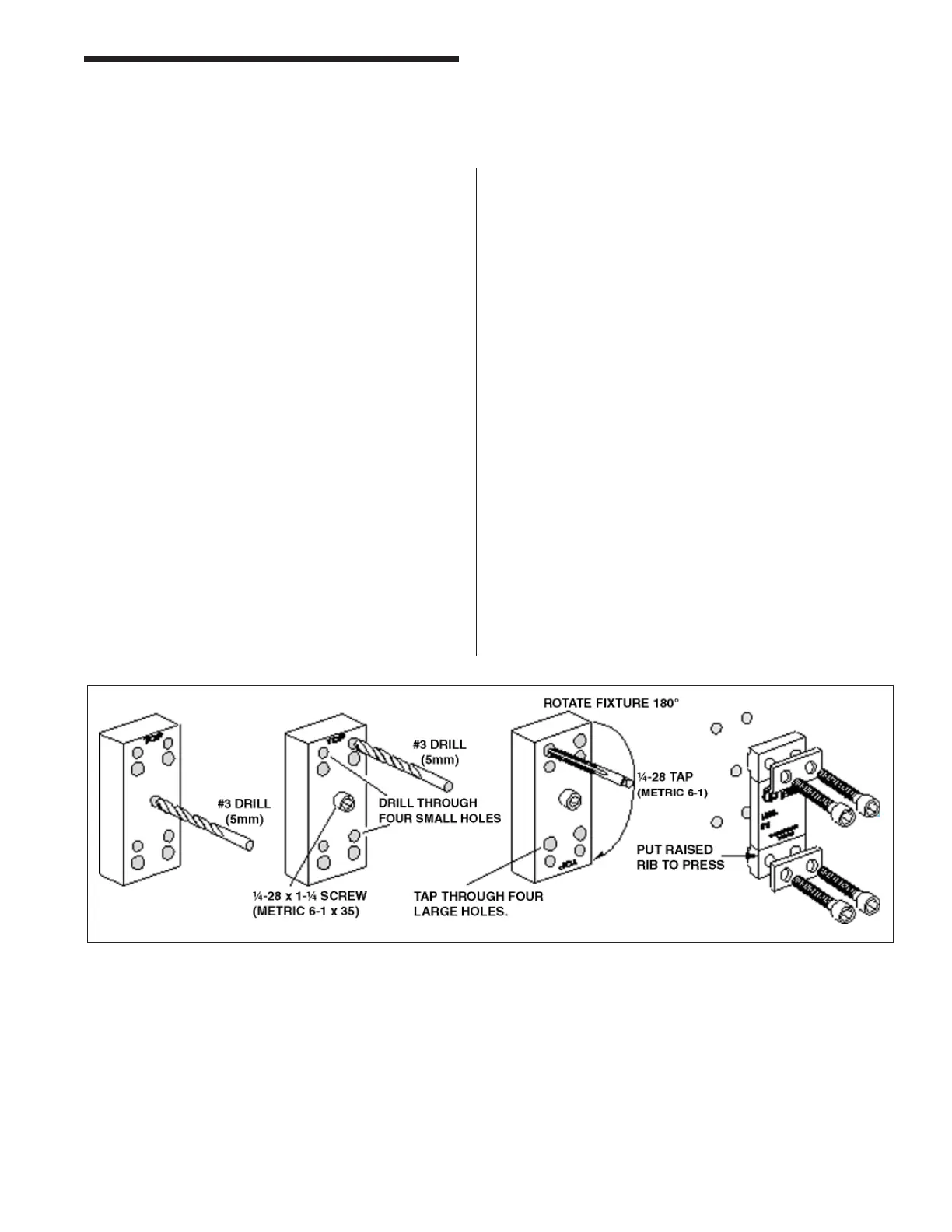
Step No. 3 Bolt the drill guide to the press member
using the 1/4-28 by 1-1/4 inch (M6-1 X
35) long socket head cap screw in the
center of the guide.
Step No. 4 Insert the number 3 drill (5mm) into the
smaller hole and drill out all four holes
to a depth of 3/4 of an inch.
Step No. 5 Loosen the drill guide. Rotate the drill
guide 180° such that the larger holes
line up with the fresh drilled holes in the
press member. Insert a tap to be sure
the holes line up. Lock the drill guide
by tightening the center socket head
screw.
Step No. 6 Insert the tap into the larger tap guide
holes and tap each hole. Be sure to
use plenty of tapping fl uid.
Step No. 7 Remove the tap guide and continue with
more holes where needed.
Step No. 8 Mount the sensor with raised rib to the
press. The anti-torque washers should
go between the screw and the sensor
body.
Tonnage Load Monitor (optional)
Installation