42
Step 10: If your PLC readout device does not adjust
the tonnage, then the TLM will need to be
adjusted.
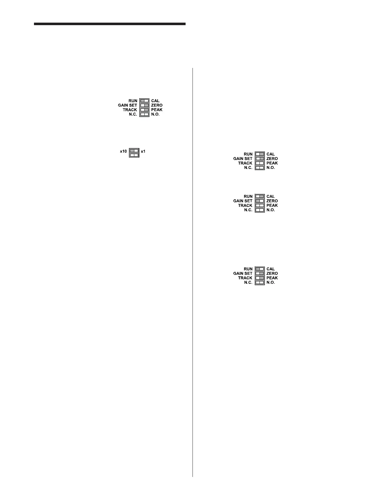
Set the mode switches to:
Adjust the gain pot after each press cycle
until your readings on the Presscam 8 match
the readings on the load cells. To obtain
more gain use the switch.
Step 11: After your readings match up, check the
tonnage at lighter values by backing off the
slide adjustment little by little and record the
results. This should be done at least four
times to see the accuracy at lower tonnages.
This is called a “linearity check.”
Step 12: You are now done with the calibration.
Refer back to the “Tonnage Setup” page
for instructions on how to setup the tonnage
limits.
Setup the TLM with Pre-calibrated
Load Cells
Follow these steps after you have installed the TLM and
place the load cell in the press (Complete the following
formulas if your TLM has anything other than a 1 meg
shunt).
Step 1: Locate the following information from the load
cell calibration data sheet:
• Shunt Output Resistance ____________
• Shunt Output Voltage in mV/V ________
Step 2: Find the New Shunt Output by completing the
following formula:
(.000001) x (Shunt Output Resistance) x
(Shunt Output Voltage) = New Shunt Output
Voltage
Step 3: Set your TLM to a Full Scale voltage. Common
settings are 5VDC or 2.5VDC. Label this V
Full Scale.
Step 4: Find voltage output at full scale on the
calibration sheet. Label this V Out Full Scale
_________.
Tonnage Load Monitor (optional)
Installation
Step 5: Find the calibration voltage by completing the
following formula:
(V Full Scale) X (New Shunt Voltage) =
Calibration Voltage Number
(V Out Full Scale)
The Calibration Voltage Number = ___________
Step 6: Switch the TLM to:
_______________________
And Adjust the balance to ZERO.
Step 7: Switch the TLM to:
And adjust the gain pot to the Calibration
Voltage Number from Step 5. You can read
this voltage with a DC voltmeter. Read from
the output of the TLM.
Step 8: Switch the TLM back to Run: