29
Regulations & Guidelines for
Safe Operation
1910.212
General requirements for all machines (covers press
brakes, hydraulic and pneumatic machines not covered
by mechanical power press standards.)
(a) Machine guarding - (1) Types of guarding. One
or more methods or machine guarding shall be
provided to protect the operator and other
employees in the machine area from hazards such
as those created by point of operation ingoing nip
points, rotation parts, flying chips and sparks.
Examples of guarding methods: barrier guards,
two-handed tripping devices, electronic safety
devices, etc.
NOTE: These are only partial reprints, refer to your
Federal Register for total construction, control reliability,
and machine guarding requirements for the subject
machine being guarded for all applicable OSHA
Standards.
ANSI StandarANSI Standar
ANSI StandarANSI Standar
ANSI Standar
ds B11.19-1990ds B11.19-1990
ds B11.19-1990ds B11.19-1990
ds B11.19-1990
Formula for calculating safety light curtain distance
from point of operation.
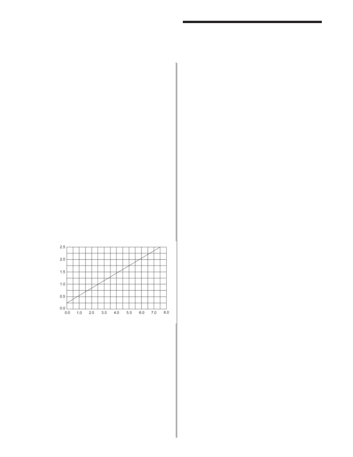
Penetration Factor D(pf) in Inches
The effective sensing field of the device shall be located
at a distance from the nearest recognized hazards such
that the operator or others cannot reach the hazard with
a hand or other body part before cessation of motion
during the hazardous portion of the machine cycle.
The point at which a device responds to an intrusion
may vary. The devices should be located or adjusted
such that the device always responds to the intrusion at
or prior to the safety distance. Care should be exercised
when installing the device to ensure that it does not detect
false signals from other devices in the area.
Usually the electro-optical presence-sensing device is
used in a manner that provides a protected zone in front
of the primary work area with auxiliary devices or guards
used to protect secondary access areas. In some cases,
however, mirrors may be used in conjunction with the
device to provide 2, 3, or 4 sided protection.
The machine stop time should be measured with the
machine running at its fastest speed with its heaviest die
or tooling and the stop time being measured at the 90º
position in the downstroke.
The following formula should be used when calculating
the safety distance:
Ds = K (Ts + Tc + Tr + Tbm )+D(pf)
Ds = Minimum safety distance between the
device and the nearest point of operation
hazard (in inches).
K = Hand speed constant. This value has been
determined by various studies and although
these studies indicate speeds of 63 in/sec
to over 100 in/sec, they are not conclusive
determinations. The employer should
determine this value by considering all
factors, including physical ability of the
operator.
Ts = Stop time of the machine tool measured at
the final control element.
Tc = Response time of the control system.
NOTE: Ts and Tc are usually measured by
a stop time measurement device.
Tr = Response time of the presence-sensing
device and its interface, if any, as stated by
the manufacturer or measured by the
employer.
Tbm = Additional time allowed for the brake monitor
to compensate for variations in normal
stopping time.
D(pf) = Added distance as indicated by the chart
above. The minimum object sensitivity is
stated by the manufacturer. If beam
blanking or floating blank features is used,
these figures should be added to the object
sensitivity figure before using the above
chart.
Blanked
Dimensions
or
Minimum
Object
Sensitivity