32
Overview
The Tonnage Load Monitor has been designed with
user friendliness in mind. The analog output of the TLM
provides a shielded/twisted pair cable to the P4 plug on
the Presscam 8 computer board. That is, each analog
output must have a ground wire twisted around it. All the
twisted pairs (up to 4) are then encased in a shield which
must be connected to the case (usually the nut holding
down the aluminum cover). The TLM should be mounted
within 3 feet. Several useful functions such as auto-
zeroing and peak hold circuits have been incorporated
to make the TLM a versatile signal conditioner.
The “counts” is a digital representation of the voltage on
the sensor input. 0 = 0v, 512 = 2.5v, 1024 = 5.0v 2.5v =
machine tonnage capacity / 4. Tonnage on all 4 channels
can be viewed while in RUN mode. The tonnage for any
channel will only be displayed on the RUN screen when
the minimum tonnage value is set above 0. You can
still only change the setpoints from the Tonnage Setup
screen in the PROG mode.
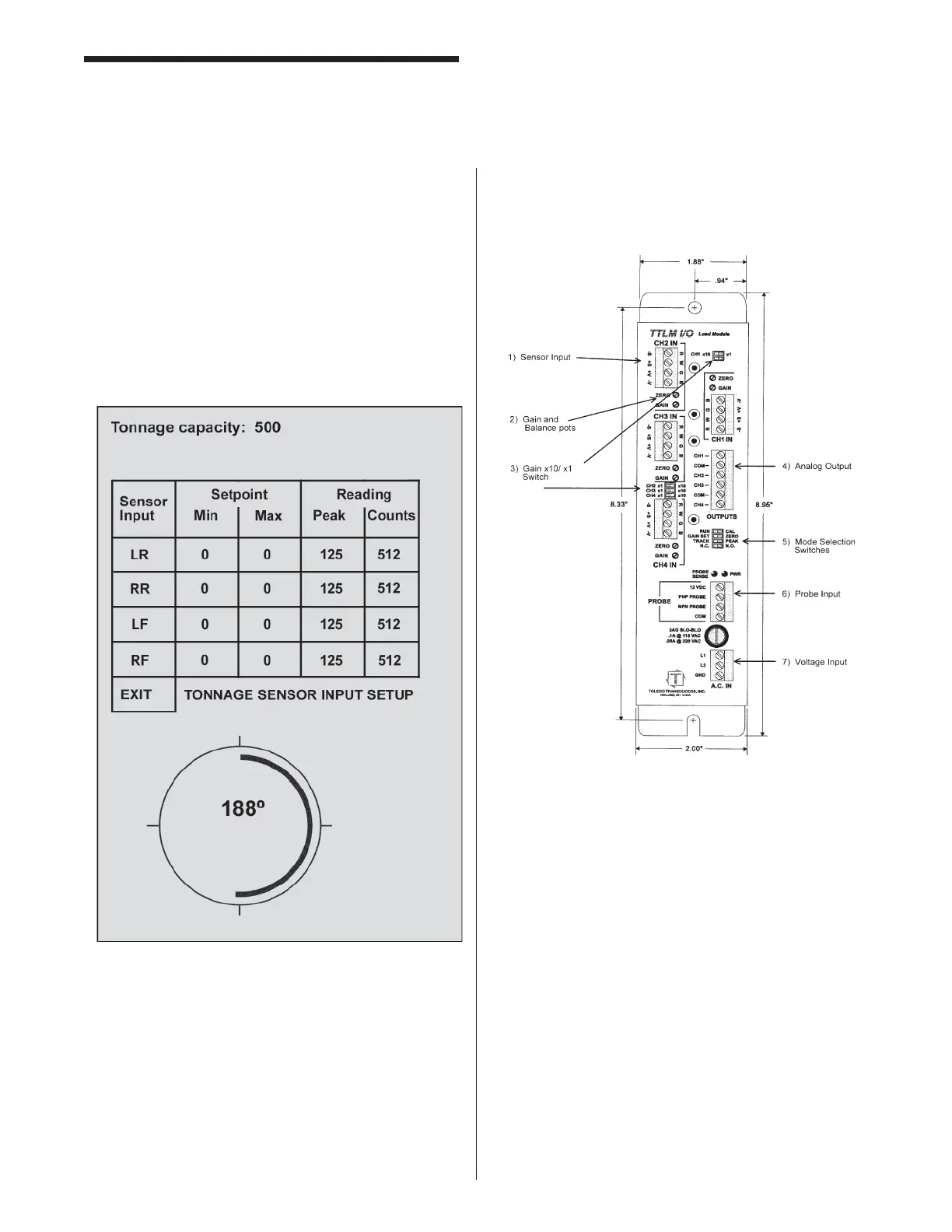
Tonnage Load Monitor (optional)
Mounting & Connecting
Mounting the TLM
Use #10 screws to securely mount the TLM in an
enclosure suited to the environment. The dimensions
and recommended mounting hole arrangements are
shown below in Figure 1.
Connecting Sensors to the TLM Sensor
Connection Guidelines
1. Strip the sensor cable as shown in Figure 2. Be
sure not to nick any of the signal conductors or
strip the shield completely away. At least a ½
inch of cable shield should be exposed for proper
insertion into the wire lug.