35
Tonnage Load Monitor (optional)
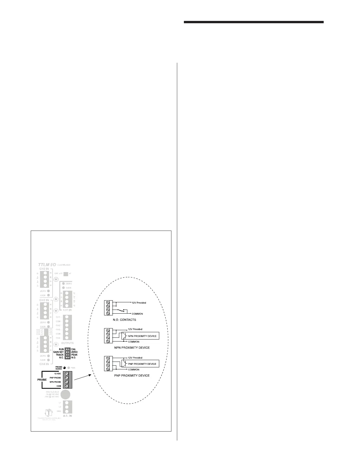
Mounting & Connecting
The probe supply voltage is provided by the TLM via
the +12VDC output connection on the PROBE interface
connector.
Figure 5 illustrates the wiring for both the PNP and NPN
probe types.
Either a normally open or normally closed probe may
be used.
The LED directly above the probe input connector
(PROBE SENSE) indicates the actual state of the probe.
This LED should turn on at 140° and turn off at 240°. If
it is working just the opposite, simply fl ip the N.C. -N.O.
Dip Switch.
If the probe is ON during this time, the DIP switch may
be moved to N.C. to invert the logic of the probe signal
in the TLM.
(* The state of the LED is not affected with this switch.)
(See Function Descriptions, “Tonnage Setup”.)
Figure 5
TLM Probe Interface Connections
 Loading...