CONTROLS/INSTRUMENTS
controlled by the Volume and Tone controls on
the front of the radio. These controls have no
effect on the passengers audio. The radio must
be in the ‘’On’’ position in order to have radio
audio available for either the passengers or the
driver.
Auxiliary
active
D
R
I
V
E
R
AUX
Muted
D
R
I
V
E
R
AUX
D
R
I
V
E
R
Radio active
FIGURE 18
5. Controlling the PA Section
The external speaker option (EXT) of the PA
section is not used as only internal speakers are
installed at the factory.
PUBLIC ADDRESS (P.A.)
Microphone jacks
There are two (2) standard PA system
microphone jacks installed on vehicle; one just
below driver's L.H. side control panel and the
other on central console. Five (5) optional
microphone jacks can be installed in the following
locations:
- One on back of modesty panel.
- One on back of driver's guard.
- One on R.H. lateral panel.
- One on lavatory's exterior front wall.
- One on parcel rack of owner's choice.
Whenever any of the microphone inputs are
activated, the control unit switches over to the PA
mode. The PA has priority over all the other
selections. When activated, all other audio is
muted and the radio cassette player is stopped.
The PA system may be activated even when the
control unit’s Power button is not activated. When
this is done, there is a short delay while the
amplifier is powering up.
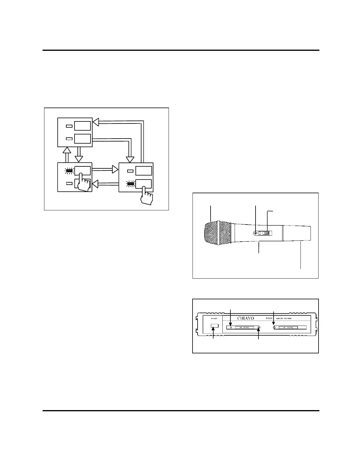
As an option, a wireless microphone (fig. 19) and
receiver (fig. 20) may also be installed. To operate
the wireless microphone, simply slide the
microphone power switch the to the ON position
and push in the receiver power switch.
The 9 volt battery of the microphone should be
replaced if the battery-low indicator (LED) stays on
when the power switch is at the ON position (if the
battery is good, the indicator will only flash once as
the switch is slid to the ON position.)
Windscreen and
ca
sule set
Battery-low indicator
Power switch
Transmitter
ack
Battery pack
FIGURE 19: WIRELESS MICROPHONE
23119
Power switch
Power pilot LED
RF signal indicator
F signal indicator
FIGURE 20 23120
The back-up PA system is provided in the event
that the PA function of the control unit is not
operating properly. Figure 21 shows the location of
the back-up PA system.
 Loading...


