8
PRODIGY
®
- DIGITAL VAV DIFFUSERS
PRODUCT OVERVIEW & INSTALLATION INSTRUCTIONS
PRICE PRODIGY
®
- Manual
|
priceindustries.com
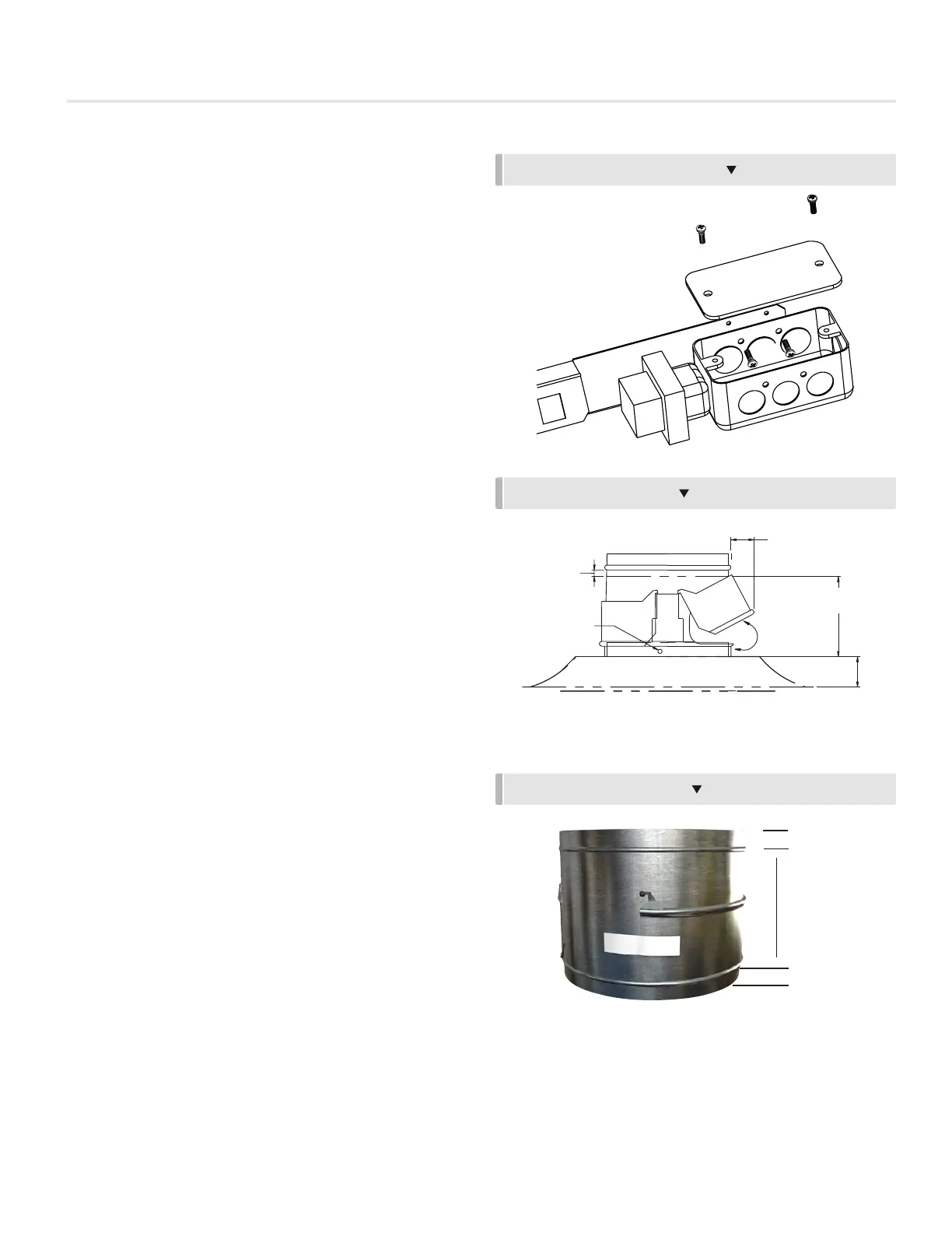
MIN. CLEARANCE REQ’D
TYPICAL INSTALLATION WITH PRODIGY DIFFUSER (SHIPPED SEPARATELY)
ADDS APPROX. 6”
HEIGHT (ALL INLET SIZES)
FREE MOVING
SHUTTER
2.5”
FLEX DUCTING
MUST NOT EXTEND
MORE THAN
1
/2”
BELOW BEAD
INSTALL OVER
PRODIGY INLET NECK
SCREW FASTENING
BY OTHERS
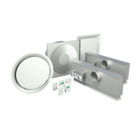
TR115 / TR277 Transformer Optional Accessory
Optional 20 VA transformer mounts to the junction bracket
of Prodigy Diffuser. Support up to 6 Prodigy units - any
combination of masters and associated drones.
Installation Instructions
1. Remove lid from junction box.
2. Fasten to Prodigy junction bracket using two #8 screws
provided.
3. Connect primary power supply and grounding.
4. Replace cover.
5. Connect secondary transformer leads to power jack of
Prodigy
(TP - Terminal Plug provided).
Additional masters units may be powered using C35 cables
and CS (cable splitters) to daisy-chain power. (Fig. 7 page 3.)
Prodigy Pressure Relief Collar Optional Accessory
(Not Available for the PLD Prodigy Linear Diffuser)
The Prodigy
®
Pressure Relief Collar (PRC) slips over the
Prodigy inlet to provide a simple and inexpensive method
to control duct static pressure. The PRC’s dual shutters are
designed to gradually open in response to pressure in excess
of approximately 0.25” w.g. and allow some of the supply air to
escape into the return air plenum.
Installation Instructions
1. The PRC is intended for use only in systems that
have a non-ducted return air plenum.
2. Mount PRC directly over Prodigy inlet, with shutters
hanging down. Two mounting holes are provided for
fastening with #8 sheet metal screws.
3. Mount ducting to top of PRC. A bead is provided on the
top of the PRC as a stop for hard ducting. Flex duct may
be banded below the bead providing it does not extend
more than
1
/2” below the stop bead as it will obstruct the
proper operation of the shutters.
4. The PRC is shipped with shutters taped shut. DO NOT
REMOVE the tape until the system is completely balanced.
This will ensure that the balancer can provide maximum
design cfm without excess air being relieved into the
plenum. Premature removal of the tape may impair proper
air system balancing.
OPTIONAL 20 VA TRANSFORMER
INSTALLATION DIAGRAM
1"
1"
6"
PRESSURE RELIEF COLLAR