3
PRODIGY
®
- DIGITAL VAV DIFFUSERS
PRODUCT OVERVIEW & INSTALLATION INSTRUCTIONS
priceindustries.com
|
PRICE PRODIGY
®
- Manual
Drone Power Supply Connection
PPDD
(See Figure 3, Figure 4, Figure 5, Figure 6)
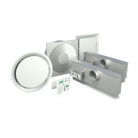
• Unit has two RJ12 Jacks to make daisy chain connections
for 24 VAC and 2-10 VDC control signal from master unit.
• C35 (35’ plenum rated cable) supplied with RJ12 modular
plugs at both ends. Use cable to connect unit with
DRONE OUT (Fig. 4) on Prodigy Master (PPD1, PPD2 or
PPD3) or previously connected PPDD using a free Drone
output Drone Jack (Fig. 5). Cable length may be extended
by using a CC (cable connector) for longer runs.
• A maximum of five PPDDs can be supported by one
Prodigy Master (PPD1, PPD2 or PPD3).
• Each PPDD draws 3.0 VA.
PPM 115 / 277 POWER SUPPLY (ONE OUTPUT JACK)
= MASTER
CS
CS
CS
CS
POWER JACK
DRONE JACK
= DRONE
USE C35 CABLES
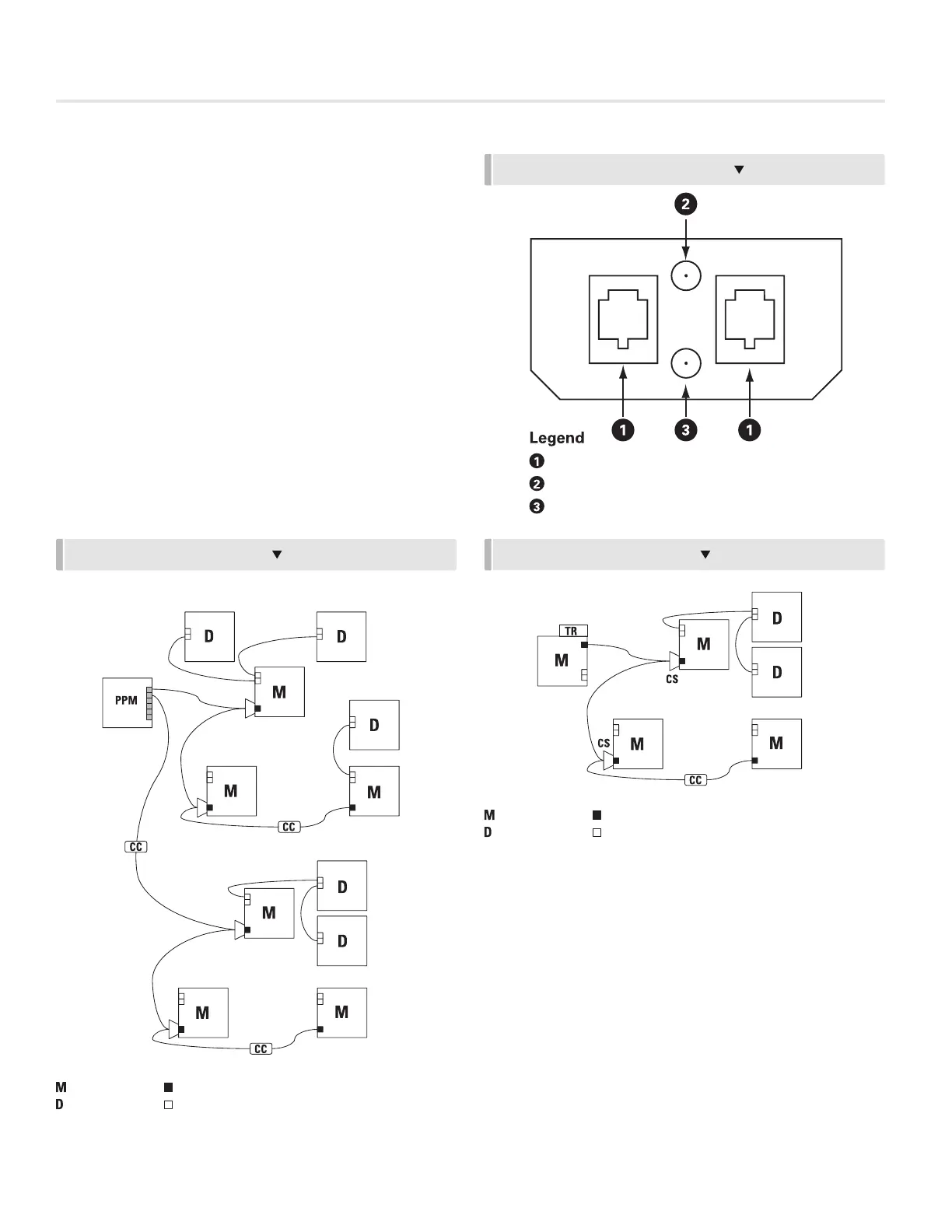
FIGURE 6 - LAYOUT EXAMPLES
FIGURE 5 - DRONE JUNCTION PANEL
DRONE INPUT / OUTPUT
RED LED (2-10 VDC DRONE SIGNAL)
GREEN LED (24 VDC POWER)
PPM 115 / 277 POWER SUPPLY (6 MAX DIFFUSERS PER JACK. 16 MAX DIFFUSERS
PER PPM)
= MASTER
POWER JACK
DRONE JACK
= DRONE
USE C35 CABLES
FIGURE 7 - LAYOUT EXAMPLES
PPM 115 / 277 POWER SUPPLY (ONE OUTPUT JACK)
TR115 / 277 POWER SUPPL
Y
= MASTER
POWER JACK
DRONE JACK
= DRONE
USE C35 CABLES
TR115 / 277 POWER SUPPLY
= MASTER
POWER JACK
DRONE JACK
= DRONE
USE C35 CABLES