5.4 OUTPUT SIGNALS
5
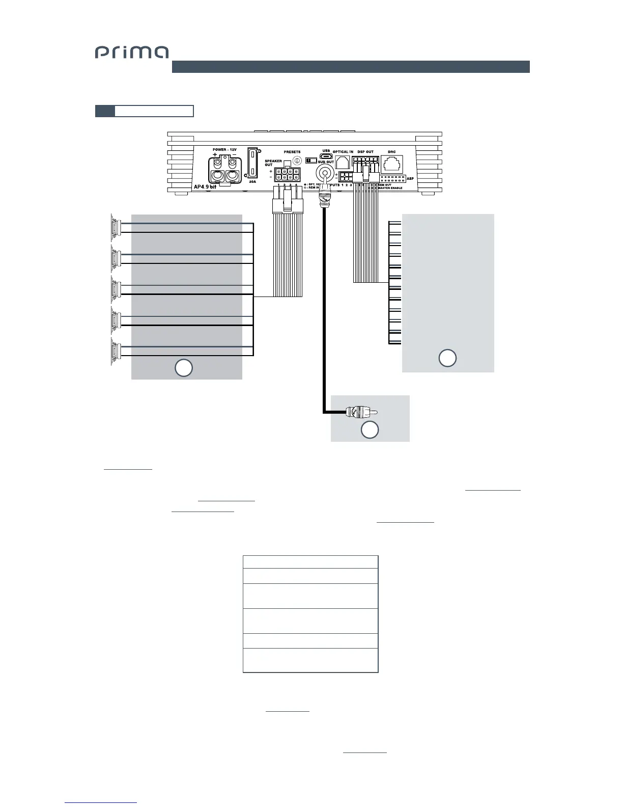
1. L’AP4.9 bit The AP4.9 bit provides 5 amplified outputs. Each output channel is configured through PC software
(see section 7.2):
- A 10-pole parametric equalizer;
- A 68-frequency electronic crossover and Butterworth or Linkwitz-Riley filters with 6-24 dB slopes
(see section 7.3.10);
- A digital time delay line
(see section 7.3.11);
- Phase inversion
(see section 7.3.10.2);
- Output level adjustment to better align the total response of the system
(see section 7.3.13);
2. The AP4.9 bit features a 12-pin DSP OUT connector to relay 4 additional channels internal to the DSP and managed
by PC software. It is possible to connect an AP4 D amplifier or a generic 4-channel amplifier to this socket
through an adapter cable. For connections see section 4.5.
3. AP4.9 bit features one DSP OUT preamplified output (4 V Rms max.) that exclusively controls a mono amplifier for
subwoofer, or one active subwoofer to amplify the sound system.
This output can be activated during the I/O Wizard Configuration (see sec. 7.2.9).
CH1÷ CH4 AMPLIFIED OUTPUT CHANNEL CONFIGURATION
STEREO MODE
POWER CHANNEL CONFIG
CH1 70 W @ 4 Ohm / 130 W @ 2 Ohm
CH2 70 W @ 4 Ohm / 130 W @ 2 Ohm
BRIDGE MODE
CH1+ 2- 260 W @ 4 Ohm
CH3+ 4- 260 W @ 4 Ohm
CH3 70 W @ 4 Ohm / 130 W @ 2 Ohm
CH4 70 W @ 4 Ohm / 130 W @ 2 Ohm
0
1
2
3
4
5
6
7
UPGRADE
OFF ON
White OUT 1+
White OUT 2+
White OUT 3+
White OUT 4+
White OUT 5+
White/Black OUT 1-
White/Black OUT 2-
White/Black OUT 3-
White/Black OUT 4-
-White/Black OUT 5-
2
3
1
1 white out 5 +
7 white/black out 5 -
2 gray out 6 +
8 gray/black out 6 -
3 green out 7 +
9 green/black out 7 -
4 violet out 8 +
10 violet/black out 8 -
5 orange SUB +
11 orange/black SUB -
6 blue REM IN
12 blue/white out 5
SUB OUT