Hardware Modifications
90
CANopen Interface Module Description
The table shows technical data for the CANopen interface module:
Connections
This interface is used to connect the Slim Panel to remote equipment, via a cable. The connector
is a D-Sub 9-pin plug connector.
By using a long PLC cable to connect to the Slim Panel, it is possible that the cable can be at an
electrical potential that is different from the electrical potential of the panel, even if both are
connected to ground.
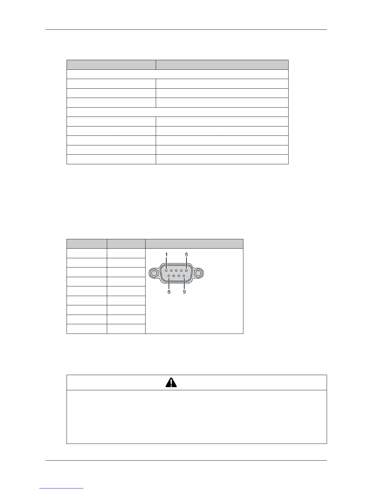
The table shows the D-Sub 9-pin assignments:
NOTE: You can set the terminator resistor by jumper setting. The position (pin 1-2) is for the value
of the terminator resistor of 120 ohm. The position (pin 2-3) is for without terminator resistor.
Any excessive weight or stress on communication cables may disconnect the equipment.
Features Values
General
Bus type Mini PCIe card revision 1.2
Connector 2 x plug D-Sub 9-pin
Power consumption 400 mA at 5 Vdc
Communication
Protocol CAN 2.0 A/B
Signal support CAN_H, CAN_L
Speed 1 Mbit/s
CAN frequency 16 MHz
Termination resistor 120 Ω (selected by jumper)
Pin Assignment D-Sub 9-pin plug male connector
1–
2CAN_L
3GND
4–
5–
6–
7CAN_H
8–
9–
CAUTION
LOSS OF POWER
Ensure that communication connections do not place excessive stress on the communication
ports of the Industrial Personal Computer.
Securely attach communication cables to the panel or cabinet.
Use only D-Sub 9-pin cables with a locking system in good condition.
Failure to follow these instructions can result in injury or equipment damage.