PS5000 Series (Slim Panel Type Atom Model) User Manual
93
NOTE: To configure the master, a GSD file (device description file) is required. The settings in the
used master must comply with the settings in the slave to establish communication. The main
parameters are: Station address, ID number, baudrate, and config data (the configuration data for
the output and input length).
Connections
This interface is used to connect Slim Panel to remote equipment, via a cable. The connector is a
D-Sub 9-pin plug connector.
If you use a long PLC cable to connect to the Slim Panel, the cable can be at an electrical potential
that is different from the electrical potential of the panel, even if both are connected to ground.
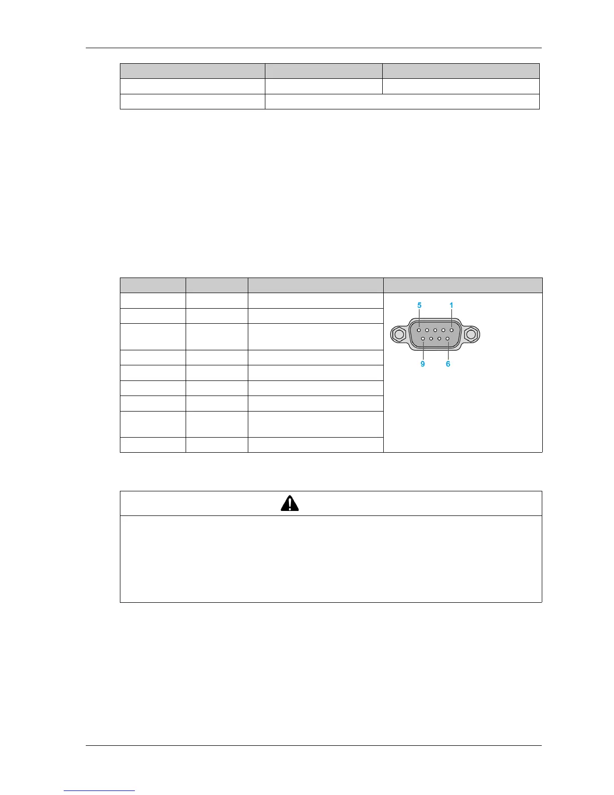
The table shows the D-Sub 9-pin assignments:
Any excessive weight or stress on communication cables may disconnect the equipment.
Device Manager and Hardware Installation
Install the driver before you install the interface module into the Slim Panel. The driver installation
media is included with the package. After the interface module is installed, you can verify whether
it is properly installed on your system through the Device Manager.
Configuration data 244 bytes 244 bytes/slave
Parameter data 237 bytes
Features Profibus DP slave Profibus DP master
Pin Assignment Description D-Sub 9-pin plug female connector
1––
2––
3 RxD/TxD-P Receive/Send Data-P
connection B plug
4––
5 GND Reference potential
6 VP Positive supply voltage
7––
8 RxD/TxD-N Receive/Send Data-N
connection A plug
9––
CAUTION
LOSS OF POWER
Ensure that communication connections do not place excessive stress on the communication
ports of the Industrial Personal Computer.
Securely attach communication cables to the panel or cabinet.
Use only D-Sub 9-pin cables with a locking system in good condition.
Failure to follow these instructions can result in injury or equipment damage.