11
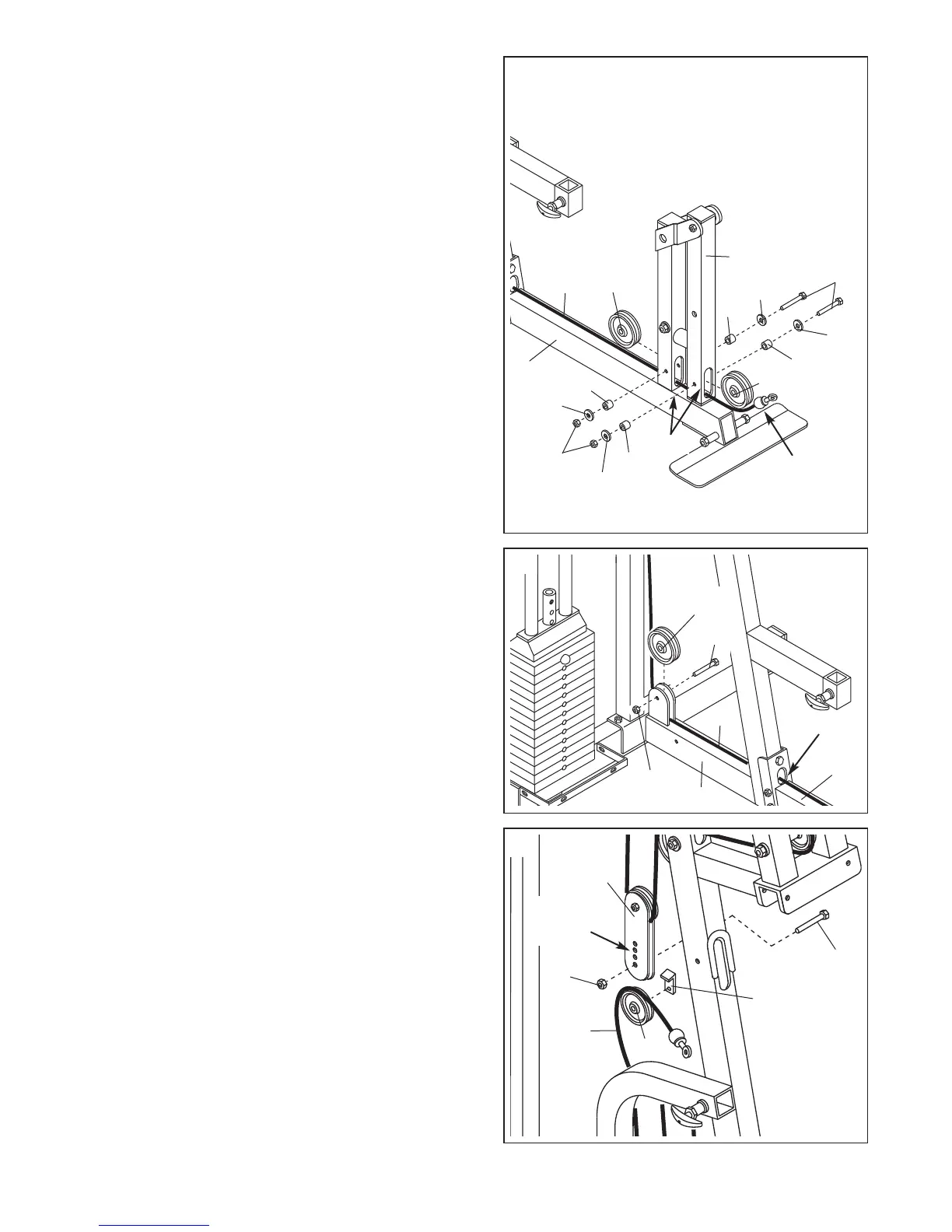
15. Route the Low Cable (72) through the indicated slot
in the Main Upright (3) and the Base (8).
Wrap the Low Cable (72) around a 4” Pulley (35) in
the direction shown. Attach the Pulley to the welded
bracket on the Main Upright (3) with a 3/8” x 2” Bolt
(62) and a 3/8” Nylon Locknut (50).
15
50
3
72
8
35
62
Slot
14. Identify the Low Cable (72), which is the only remain-
ing cable. Note that it has a large ball on one end and
a small ball on the other.
Route the small ball on the Low Cable (72) through
t
he indicated slots in the Leg Lever (29) and the front
leg on the Base (8).
Attach a 4” Pulley (35) inside the slot in the Leg Lever
(29) with a 3/8” x 2 1/2” Bolt (54), two 3/8” Flat
Washers (55), two Pulley Bushings (42), and a 3/8”
Nylon Jamnut (63).
Attach a 4” Pulley (35) inside the slot in the front leg
on the Base (8) with a 3/8” x 2 1/2” Bolt (54), two 3/8”
Flat Washers (55), two Pulley Bushings (42), and a
3/8” Nylon Jamnut (63).
14
55
42
72
42
55
29
35
8
63
Slots
Larger Ball
42
55
42
55
54
35
16. Wrap the Low Cable (72) over a 4” Pulley (35). Attach
the Pulley and the Cable Trap (44) to the lowest
adjustment hole in the Pulley Plates (31) with a 3/8” x
1 3/4” Bolt (60) and a 3/8” Nylon Jamnut (63). Make
sure that the Cable is in the groove of the Pulley
and that the Cable Trap is oriented as shown, so
it will hold the Cable in place.
16
31
Adjustment
Holes
63
60
35
44
72