10
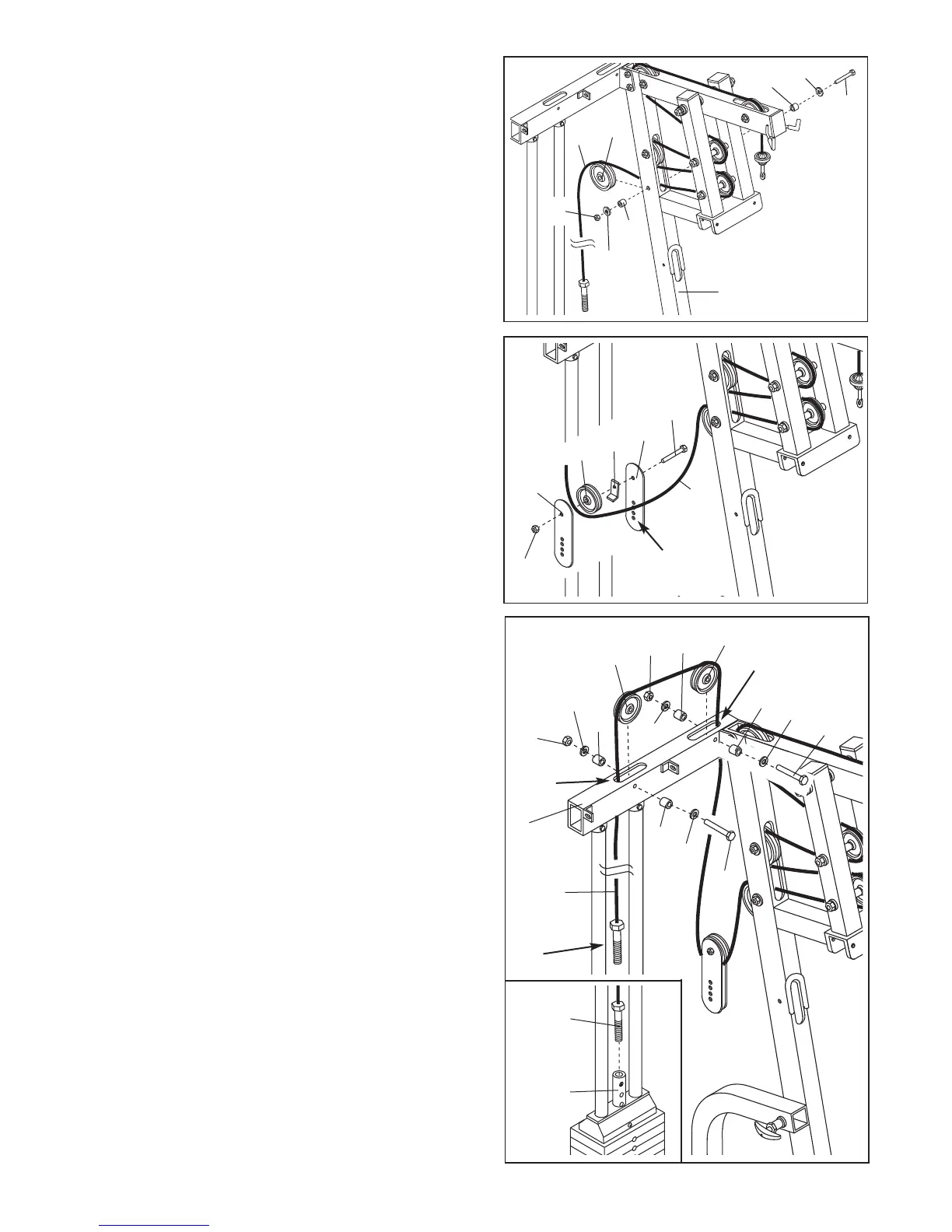
12. Disassemble the Pulley Plates (31). Note that on one
end the Pulley Plates have several adjustment holes.
These holes must be closest to the floor.
Wrap the High Cable (73) under a 4” Pulley (35).
Attach the Pulley to the upper ends of the Pulley
Plates (31) with a 3/8” x 1 3/4” Bolt (60), a Cable Trap
(44), and a 3/8” Nylon Jamnut (63). Make sure that
the Cable is in the groove of the Pulley and that
the Cable Trap is oriented as shown, so it will
hold the Cable in place.
Set the other 4” Pulley, 3/8” x 1 3/4” Bolt, Cable Trap,
and 3/8” Nylon Jamnut aside (these parts are not
shown).
12
73
60
31
44
35
31
63
Adjustment
Holes
13. Feed the bolt on the High Cable (73) up through slot
A in the Top Frame (1) as shown.
Lay the High Cable (73) over a 4” Pulley (35). Attach
the Pulley inside slot A with a 3/8” x 2 1/2” Bolt (54),
two 3/8” Flat Washers (55), two Pulley Bushings (42),
and a 3/8” Nylon Jamnut (63).
Lay the High Cable (73) over another 4” Pulley (35)
and feed the bolt on the High Cable down through
slot B in the Top Frame (1) as shown. Attach the
Pulley inside slot B with a 3/8” x 2 1/2” Bolt (54), two
3/8” Flat Washers (55), two Pulley Bushings (42), and
a 3/8” Nylon Jamnut (63).
See the inset drawing. Thread the bolt on the High
Cable (73) two turns into the top of the Weight Tube
(36).
13
1
42
55
35
35
42
55
54
63
42
63
73
42
55
54
55
Bolt
Slot B
Slot A
11. Wrap the High Cable (73) around a 4” Pulley (35).
Attach the Pulley inside the Main Upright (3) with a
3/8” x 2 1/2” Bolt (54), two 3/8” Flat Washers (55), two
P
ulley Bushings (42), and a 3/8” Nylon Jamnut (63).
11
55
42
6
3
3
35
42
55
54
73
73
36