4
ASSEMBLY
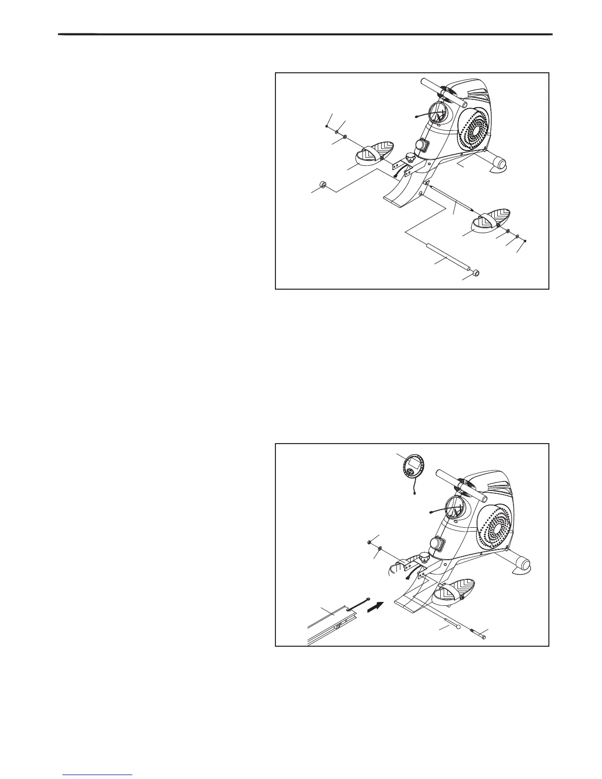
4. Attach the Nylon Nut (#12) to the end of
the left hand side of the spindle bar (#8), and
then slide onto the bar from the right the washer
(#15), followed by the plastic bushing (#18) then
the footrest (#10). Then slot the part assembled
spindle bar through the hole in the main housing
(per FIG 4.).
Now start to assemble the right hand pedal onto
the spindle bar (#8). Slide the pedal (#10) onto
the right hand side of the pedal spindle bar fol-
lowed by the plastic bushing (#18), the washer
(#15) and nally the M8 Nylon nut (#12).
Lock the pedals (#26) to the crank cover on main
housing (per FIG 4.)
Attached the Sponge (#20) to left side of the foot-
rest shaft (#9), then slot the footrest shaft (#9)
through the hole in the holder bracket cover and
attached another Sponge(#20) to the other side
of the bar.
5. Connecing the sensor wires which are on
the Rail and Main housing together, then slide the
Aluminum Rail (#5) into the main housing (per
FIG 5) and bolt into place using the xing bolt
(#27), once the bolt is slotted through the near-
est pre-drilled hole to the main housing attach the
washer (#16) and the thin Nylon nut (#17).
Using the second pre-drilled hole away from the
main housing slot through your Pull pin (#27).
Finally, Screw the xing knob into the Aluminum
Rail (#5) using the pre-drilled hole provided.
Connect the sensor wire and place the monitor
(#11) onto the main frame.