32
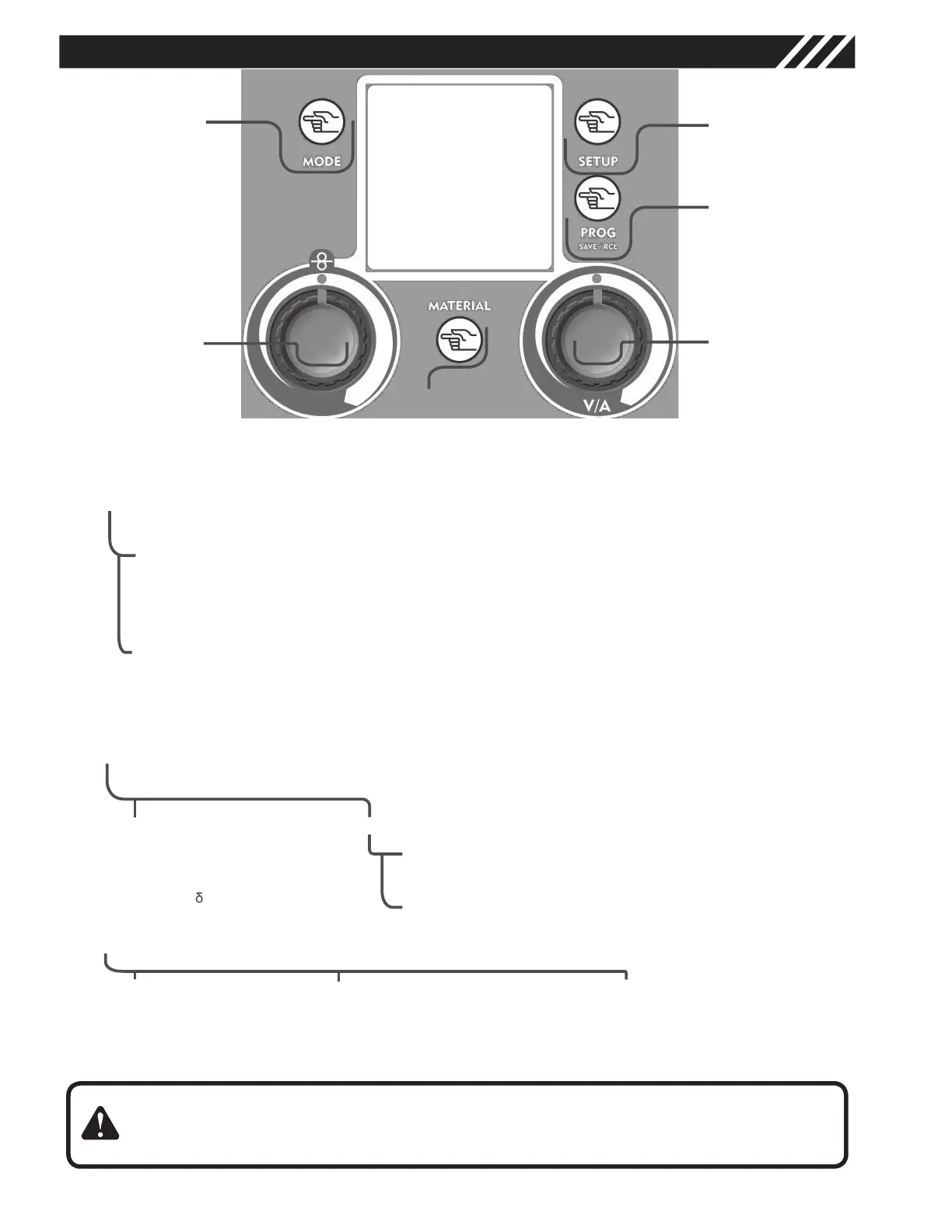
CONTROL INTERFACE
MODE Key works as BACK key in all menus.
SETUP Key allows to run through the menus by selecting in sequence the modifiable parameters.
The right knob changes the size value previously selected with the SETUP Key.
Graphic Display
Mode Key
• welding process selection
• return to the main screen after parameters setting
1
3
1
2
Setup Key
setting of the secondary parameters in all welding processes
3.1 Tig Function
2stroke/4stroke, Slope Up (0-10 sec), Slope Down (0-20 sec), crater Filler value in 4stroke function only, Post Gas
Time 0-5 sec
3.2 Mig/Mag Function
Synergy: OFF /ON/PULSED, 2Stroke/4Stroke/Spot welding, Spot Time, Motor Slope, BBT, Electronic Inductance,
Post Gas, Crater Filler
3
4
Prog save & recall Key
saves and recalls the functioning points that may be changed by the operator
4
5
5
6
7
Right Regulation Knob ( Volts / Amps)
Main Regulation Knob
Material Key
submenus selection key
6
6.1 TIG
• NORMAL
• PULSED:
• Pulsation Frequency
• ( Ton)
• I Max (peak current)
• I Min (base corrent)
6.2 MIG/MAG
6.2.1 Manual Mig/Mag (synergy OFF)
Adjustment of the electronic inductance value
6.2.2 Synergic Mig/Mag/ Synergic Pulsed
Screen access for the synergic program selection
7
Left Regulation Knob
7.1 MMA
• HOT START
7.2 TIG
• Slope Down ( Tig )
• Pulsation Frequency (Pul-
sed Tig)
7.3 MIG/MAG
• Wire speed ( Mig )
• Balance (Synergic and
pulsed Mig)
2
Figure 7
10