Technician Setup Menu
Technician Setup Menu
14
15
16
13
This feature allows the installer
to change the calibration of the
room temperature display. For
example, if the thermostat reads
70˚ and you would like it to read
72˚ then select +2.
OFF
This feature will ash a reminder
after the elapsed run time to
remind the user to change the
lter. A setting of “OFF” will
disable this feature.
Filter Change
Reminder
You can adjust the lter
change reminder from “OFF”
to 2000 hours of runtime in
50 hour increments.
Tech Setup Steps
Room
Temperature
Calibration
0˚F
You can adjust the room
temperature display to read
up to 4˚above or below the
factory calibrated reading.
Adjustment Options Default
LCD Will Show
FILTER
OF
0
This thermostat has a technician setup menu for easy installer
conguration. To set up the thermostat for your particular application:
1. Press the MENU button.
2. Press and hold the TECH SET button for 3 seconds. This 3
second delay is designed so that homeowners do not accidentally
access the installer settings.
3. Congure the installer options as desired using the table below.
Use the or keys to change settings and the NEXT
or PREV key to move from one step to another.
Note: Only press the DONE key when you want to exit the
Technician Setup options.
4. Press the DONE key to exit.
Tech Setup Steps Adjustment Options Default
LCD Will Show
This setting will select the
terminal for medium fan speed
operations. The selected terminal
cannot be used for reversing valve
operations when heat pump is
enabled.
Use the and buttons to
select O/B terminals.
0
0
The swing setting often called
“cycle rate”, “dierential” or
“anticipation” is adjustable. A
smaller swing setting will cause
more frequent cycles and a larger
swing setting will cause fewer
cycles.
Cooling
Swing
The cooling swing setting
is adjustable from 0.2˚ to
2˚. For example: A swing
setting of 0.5˚ will turn the
cooling on at approximately
0.5˚ above the setpoint
and turn the cooling o at
approximately 0.5˚ below
the setpoint.
The swing setting often called
“cycle rate”, “dierential”, or
“anticipation” is adjustable. A
smaller swing setting will cause
more frequent cycles and a larger
swing setting will cause fewer
cycles.
Heating
Swing
0.5
0.5˚
The heating swing setting is
adjustable from 0.2˚ to 2˚.
For example: A swing setting
of 0.5˚ will turn the heating
on at approximately 0.5˚
below the setpoint and turn
the heating o at 0.5˚ above
the setpoint.
0.4˚
0.4
Swing Setting Tip
The second stage will turn on at 2x the swing setting. The second stage will
turn o when 1x the swing is reached. For example, if the swing setting is .5
degrees for heating and the thermostat is set at 70˚F, the rst stage will turn
on at approximately 69.5˚F. The second stage will turn on at 69˚F. The second
stage will turn o at 69.5˚F and the rst will turn o at 70.5˚F. If the third
stage is used, it will turn on at 68.5˚F and turn o at approximately 69˚F.
COOL SWING
HEAT SWING
MED FAN TERM
CALIBRATE
PTAC Mode
This setting allows the thermostat
to operate a PTAC. This will allow
for multiple fan speeds selectable
in the next two tech settings.
Use the and buttons to
select ON/OFF.
OFF
OF
PTAC MODE
This setting allows you to choose
the number of fan speeds the
thermostat will control.
G = Low Speed Fan
B/O = Medieum Speed Fan
Y2 = High Speed Fan
PTAC Fan
Speeds
(Only displayed
if PTAC mode is
“ON”)
2
2
FAN SPEEDS
When turned on the thermostat
will operate a heat pump. EM.
Heat will show as an option in the
system switch tech setting.
Use the and button to
adjust.
Heat Pump
OFF congures the
thermostat for conventional
systems.
ON congures the
thermostat for heat pump
systems.
OFF
OF
HEAT PUMP
Use the and buttons to
select , 2 or 3.
1. Speeds: ON, Auto
2. Speeds: Low, High, Auto
3. Speeds: Low, Med, High,
Auto
Default Heat Heat Options Cool Default
Cool Options
PTAC (conventional)
PTAC (Heat Pump)
Heat Pump
Conventional
System Mode
1
2
2
2
1
2, 1
5, 4, 3, 2, 1
2, 1
1
1
2
2
1
1
3, 2, 1
3, 2, 1
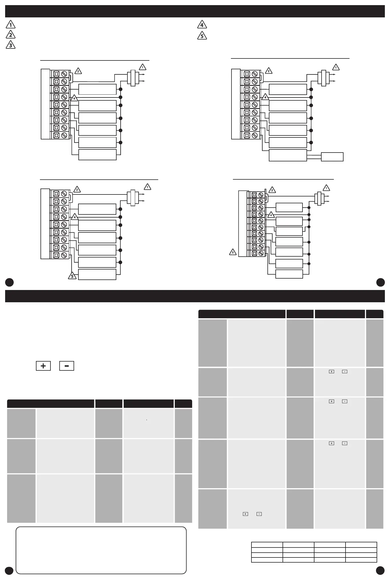
Typical 2H/2C system with 24 VAC Humidier
Typical 2H/2C system with Dehumidify Terminal
L2
L1(HOT)
C
R
RC
RH
Y
C
G
W/E
W2
Y2
H
COMPRESSOR
RELAY
HUMIDIFIER
HEAT RELAY
FAN RELAY
HEAT RELAY 2
COMPRESSOR
RELAY 2
RC
RH
Y
C
W/E
G
W2
Y2
D
COMPRESSOR
RELAY
HEAT RELAY
FAN RELAY
HEAT RELAY 2
COMPRESSOR
RELAY 2
DEHUMIDIFIER
RELAY
L2
L1(HOT)
C
R
Typical 2H/2C system with Dry Contact Humidier
RC
RH
Y
C
W/E
G
W2
Y2
H
COMPRESSOR
RELAY
24V RELAY
NORMALLY-OPEN
TERMINALS
HEAT RELAY
FAN RELAY
HEAT RELAY 2
COMPRESSOR
RELAY 2
L2
L1(HOT)
C
R
DRY CONTACT
HUMIDIFIER
HUM
HUM
Wiring Diagrams Wiring Diagrams
Power supply
Factory - installed jumper. Remove only when installing on 2 transformer systems.
Use either O or B terminals for changeover valve.
A 24 VAC common connection is required with this thermostat.
If DEHUM relay requires a normally-energized input, set Dehumidify relay to NC
in Technician Setup.
Typical 5H/3C Heat Pump System
RC
RH
Y
C
W/E
G
W2
Y2
COMPRESSOR
RELAY 1
FAN RELAY
AUXILIARY
HEAT 2
COMPRESSOR
RELAY 2
AUXILIARY
HEAT 1
C
R
L2
L1(HOT)
O
B
COOL
CHANGEOVER OR
COMPRESSOR 3
HEAT
CHANGEOVER OR
COMPRESSOR 3
PTAC Medium
Fan Speed
Terminal
(Only displayed
if PTAC mode is
ON and PTAC fan
speeds is set to 3)
 Loading...