14
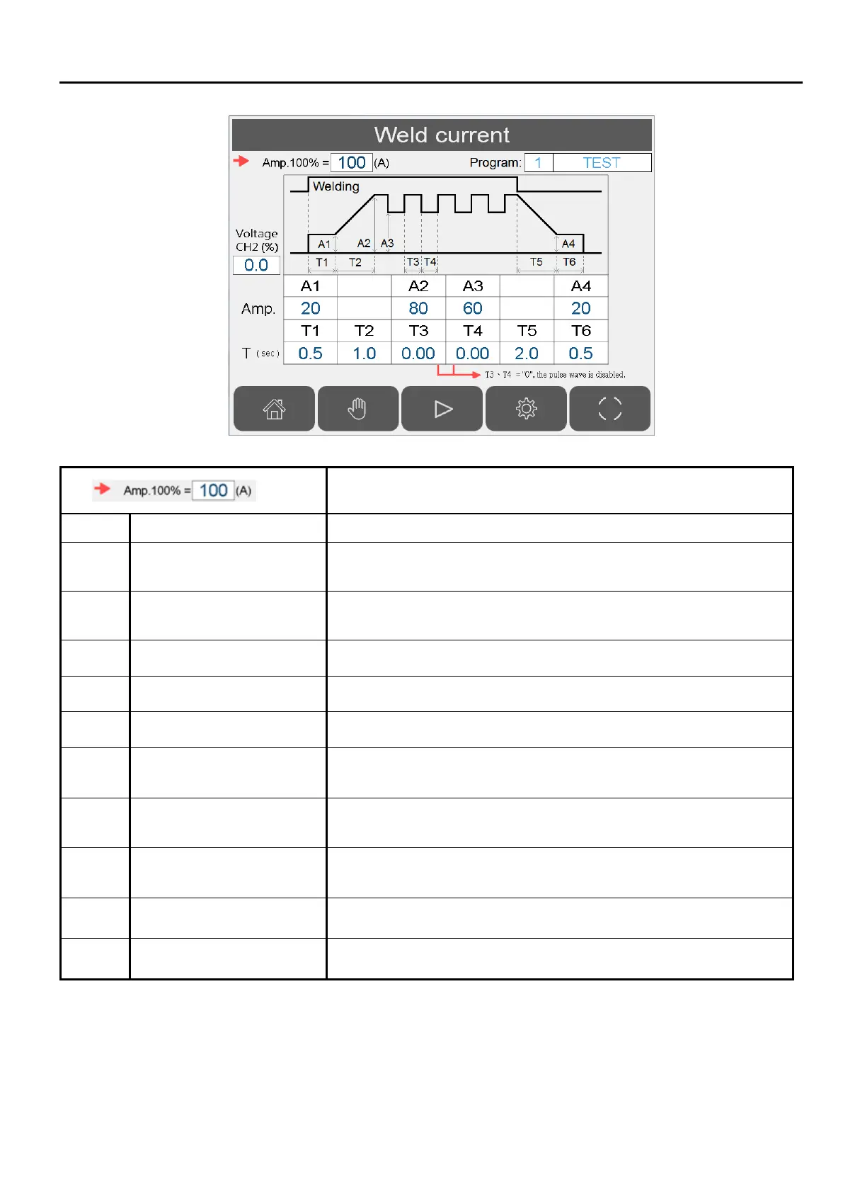
2.9 WELDING CURRENT SETTING
100% amperage value setting (analog output 1).
A1 Initial current (A) Initial current level after arc ON signal is received.
A2 Peak current (A)
Main welding current. If pulse wave function is enabled, this
value is the peak current value.
A3 Valley(low) current(A)
If pulse wave function is enabled, this value is the low current
value. Can’t set more than A2.
A4 Welding crater current(%) Welding ending current.
T1 Initial current time(sec) 0~10 sec, initial arc stabilize time after arc ON signal is received.
T2 Rise current time(sec) 0~10 sec, rise time from initial current A1 to peak current A2
T3 Peak current time(sec)
0.01~10 sec, peak current duration before change to valley
current.
T4 Valley current time(sec)
0.01~10 sec, valley current duration before change to peak
current.
T5 Current fall time(sec)
0~10 sec, amount of time current drop from A2 to A4. The count
starts after welder output is switched off. \
T6 Welding crater time(sec) 0~10 sec, amount of time for crater current.
CH2 Analog voltage(%) Channel 2 analog voltage 0~100% = 0~10VDC.
Note 1: If both T3 & T4 are set to 0, the wave pulse function is disabled.
Caution: Even though pulse wave function’s output voltage can reach a frequency of 50Hz, the
welder may not be able to change current at this rate.