EasyManua.ls Logo

ProArc PT-200s - User Manual

ProArc PT-200s
39 pages
Print Icon
To Next Page IconTo Next Page
Loading...
OPERATION MANUAL
ImportantRead these instructions before installing, operating or servicing this product.
MODEL
PT200s
WELDING POSITIONER
Serial Number
202103005 ~ Later
Revised Date
Apr. 07, 2021
UNITED PROARC CORPORATION
No. 3 Gungye 10
th
Road, Pingjen Ind. Park Tel No: 88634696600
Pingjen City, Taoyuan 324, Taiwan Fax No: 88634694499
http://www.proarc.com.tw E-Mail: customerservice@proarc.com.tw
RD-8480E
Question and Answer IconNeed help?

Do you have a question about the ProArc PT-200s and is the answer not in the manual?

Summary

Instruction and Identification

Equipment Identification

Locate and record the unit's identification number, model, and serial number.

Equipment Receipt and Inspection

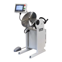
Inspect equipment upon arrival for completeness and shipping damage.

Safety Precautions and Protection

Limited Warranty Terms

Technical Specifications Overview

Control Box Specification Details

Electrical Connector Configurations

HMI Operation and Controls

Pulse Adjustment Knob Functionality

Details on using the knob for parameter adjustments like speed and amperage.

Main Screen Navigation and Access

Screen and Language Selection

Switch between languages and navigate to Manual, Auto, Settings, or System Info screens.

Auto Mode Access Requirements

Access to Auto Mode requires user clearance and default passwords.

System Settings and Configuration

Program Management Options

Access to Program, Note, and Backup screens for data management.

Operation Parameter Settings

Configure Sequence, Current, Index Weld, and Autorun functions.

System and Security Settings

Manage System Information, Password, and updates.

Welding Sequence Timing Parameters

Sequence Step T1: Welder ON Delay

Defines the delay before the welder activates after auto start.

Sequence Step T2: Table Rotation Delay

Sets delay for turn table rotation after receiving arc signal.

Sequence Steps T3-T5: Output Delays

Configures ON delays for dry contact outputs 1, 2, and 3.

Sequence Steps T6-T7: Stop & OFF Delays

Sets delays for welder OFF and table stop after target position.

Sequence Steps T8-T10: Output OFF Delays

Configures OFF delays for dry contact outputs 1, 2, and 3.

Welding Current Configuration

Amperage Settings (A1-A4)

Configuration of initial, peak, valley, and crater current levels.

Current Time Settings (T1-T6)

Defines durations for current rise, peak, valley, fall, and crater.

Analog Voltage Output (CH2)

Setting the second analog voltage output as a percentage.

Index Welding Setup

Number of Index Welds (n)

Specifies the total number of repeated welding cycles.

Welding Segment Parameters (a~b)

Sets the angle and speed for the welding portion of the index.

Positioning Segment Parameters (b~c)

Sets the angle and speed for moving to the next weld position.

Autorun Functionality Configuration

Arc Signal Feedback for Rotation

Controls turn table rotation based on arc signal input.

Start Sequence and Position Control

Defines auto start behavior and table position reset.

Foot Switch Operation Modes

Configures the foot switch for rotation control and auto start activation.

Password Management and Security

System Access Control

Setting and managing user-level passwords for system access.

Auto Mode Security Settings

Enabling or disabling password protection for Auto Mode.

Program Data Backup and Transfer

System Settings and Adjustments

Time and Brightness Adjustment

Setting the system clock and screen brightness level.

Touch Screen Calibration Procedure

Steps to calibrate the touch screen for accurate operation.

Unit Selection and Speed Limits

Choosing measurement units and defining rotation speed limits.

System Information and Maintenance

Viewing System Component Details

Information on motor, HMI, and PLC software versions and files.

Firmware Update Procedures

Instructions for updating HMI and PLC firmware.

Monitoring and History Access

Accessing I/O status monitor and alarm history logs.

HMI Firmware Update Process

PLC Firmware Update Process

Alarm History Interpretation and Logging

Input;Output (I;O) Status Monitoring

Error Message and Alarm Handling

Alarm Window Operation and Reset

Managing the alarm display, resetting errors, and handling persistent issues.

Closing Alarms Without Resetting

Procedure for dismissing the alarm window when errors remain.

Troubleshooting Common Errors

Servo Amplifier Parameter Settings

PT-200 s Mechanism Parts List

HMI Box Components List

Control Box Internal Components List

Main Power Circuit Diagram

Turn Table Servo Control Circuit Diagram

Delta DVP28 SV11 T2 Control Circuit Diagram

ProArc PT-200s Specifications

General IconGeneral
Power SourceInverter
Protection ClassIP21S
Input Voltage220V ±15%
CoolingAir-cooled
Duty Cycle60% at 200A