H - I - J FREQUENCY CONVERTERS INSTRUCTION MANUAL 0,55 ÷ 200 kW
- 10 -
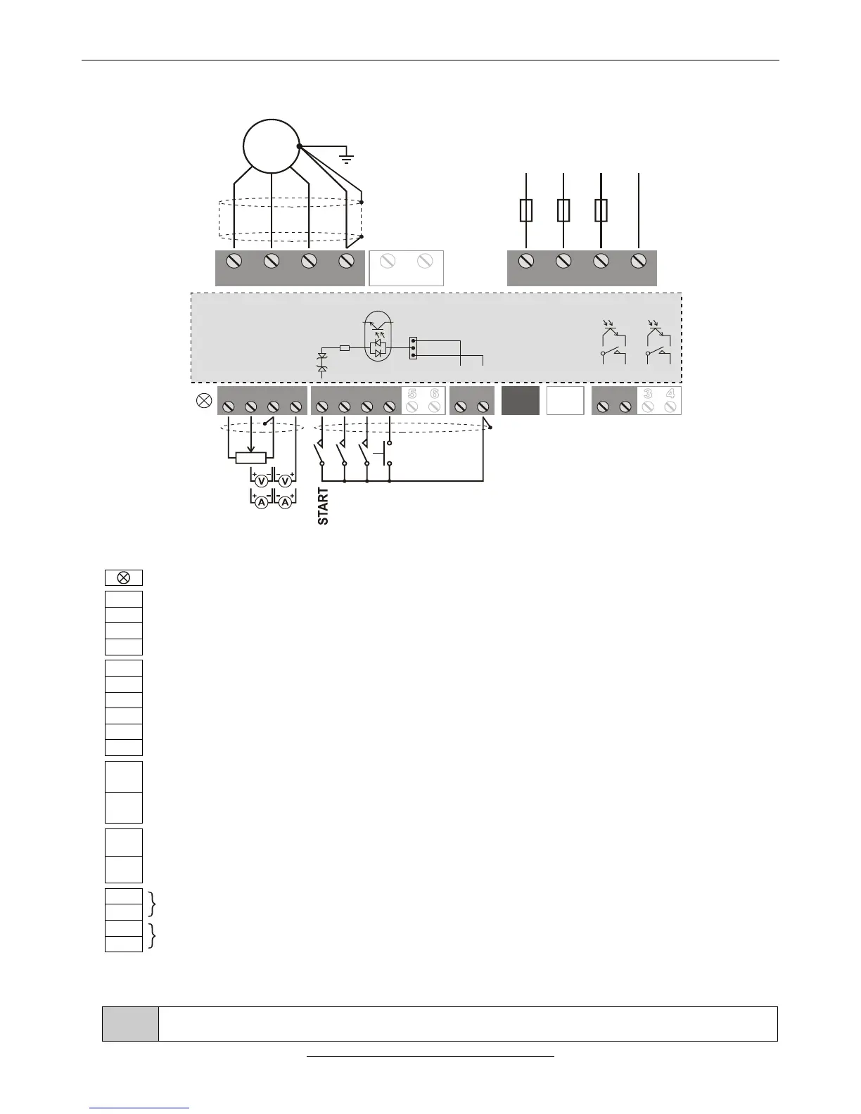
ASSIGNMENT AND CONNECTION OF THE V3D TERMINAL BLOCK
1 1 112 2 223 34 4
SA SD ST CST CSR SR
U V W PE L1 L2 L3 PE
3 x 400VAC
MOTOR
R BRAKE
LINE
2-10K
0÷10V
(0)4÷ 02 mA
REVERSING
JOGGING
ERROR A.
GND/D
M
~
F1 F2 F3
PNP
NPN
12V
12V
1K2
+24V/D
GND/D
Three-colour LED (green: On, yellow: Operate, red: Error)
+10 V potentiometer driving output (max. 6 mA) (+15 V option)
Analogue input 1: potentiometer (2÷10 kΩ), 0÷10 V (200 kΩ), 4÷20 mA (0÷20 mA) (200 Ω)
GND/A (reference point of the analogue inputs)
Analogue input 2: potentiometer (2÷10 kΩ), 0÷10 V (200 kΩ), 4÷20 mA (0÷20 mA) (200 Ω)
Digital input 1 * (factory setting: start switch)
Digital input 2 * (factory setting: reversing switch)
Digital input 3 * (factory setting: jogging)
Digital input 4 * (factory setting: error acknowledgement)
Option (Digital input 5 *, or IRE(A) input)
Option (Digital input 6 *, or IRE(B) input)
+24 V/D supply voltage output (max. 100 mA)
In case of PNP logic the common point of the digital inputs (K1, K2 jumpers)
GND/D (the reference point of the +24 V/D supply voltage output)
In case of NPN logic the common point of the digital inputs (K1, K2 jumpers)
Terminal serial line connector (CAN option, e.g. Master/Slave)
Option (System serial line and/or CAN)
Digital output 1 ** (factory setting: ready)
Option (Digital output 2 **) (factory setting: operate)
* Switching level of the digital inputs: 0.6 to 2 mA
** Digital outputs: relay (max. 250 V AC / 1 A or 30 V DC / 0,5 A) or optocoupler (optional) (max. 30 V DC / 10 mA)
The analogue inputs 1 and 2 (or analogue inputs 3 and 4) are not equipped with own terminals. If the
configuration includes them, they are connected to the terminals of other functions (mostly to SD5 and 6)