H - I - J FREQUENCY CONVERTERS INSTRUCTION MANUAL 0,55 ÷ 200 kW
- 15 -
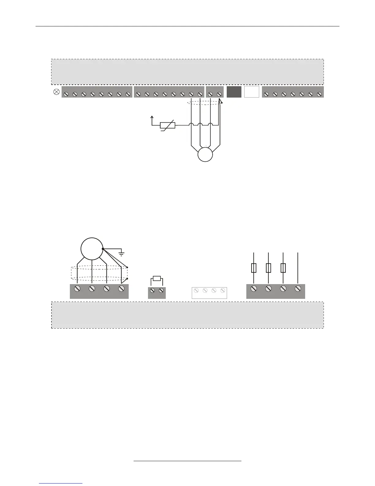
• Connections of the incremental rotation speed encoder (IRE) (optional) and thermal protection of
the motor
1 1 12 2 23 34 45 5 76 6 87 8
SA SD ST CST CSR
VLD / VHD frequency converter
1 2 3 4 5 6 7
SR
A
B
+24V
GND
IRE
PTC or
thermal
contact
The signal device can be NPN open collector type, TTL push-pull type or an output with an output voltage of 5 to 24 V.
Independently of the signal transmitter input, the further digital inputs can be operated with both negative and
positive logic circuitry.
The input selected for the connection of the PTC or the thermal contact has to be provided with “External error”,
“opening”.
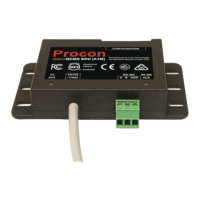
• Connecting the brake resistor (optional, in case of built-in brake chopper)
U V W PE L1 L2 L3 PE
MOTOR
LINE
VLD / VHD frequency converter
3 x 400VAC
F1 F2 F3
R BRAKE FAN
M
~
The power on the brake resistor (Pnominal / 50 ÷ Pnominal) depends on the braking time and the duty factor.
Selection guide on page 20.