H - I - J FREQUENCY CONVERTERS INSTRUCTION MANUAL 0,55 ÷ 200 kW
- 5 -
FUNCTIONING
The alternating voltage from the power line is rectified by a line diode bridge, then electrolytic capacitors smooth
out the pulsating voltage. The intelligent IGBT end stage, driven with sinusoidal modulated pulses, delivers to the
motor a voltage of variable amplitude and frequency. Following the description of the programming, until the motor
reaches its nominal revolution the voltage vs. frequency relation can optionally be changed, according to the
character of the load. (Linear, quadratically modified or knee point characteristics can be programmed.)
At low frequencies the ohmic resistance of the motor winding can be compensated (U boost).
Below the nominal revolution the frequency converter is capable of delivering nominal torque; beyond it the
converter delivers constant power.
The converter can be equipped with an optional braking resistor.
DECLARATION OF CONFORMITY
The frequency converters have been manufactured with considering following directives:
Electromagnetic Compatibility (EMC) directive
EN 13849-1:2008
EN 61800-5-2:2016
EN 60034-1:2017
EN 61800-5-1:2007
EN 60664-1:2008
EN 61800-3:2017
These products serve for being mounted into machineries.
These products are allowed to be put into service only after the machinery comprising the product was found to
comply with the above directives about machineries.
According to the directions on electromagnetic compatibility (EMC) the listed products are not considered as
products which can be operated alone. The electromagnetic compatibility can only be evaluated after the product
was incorporated in the whole system. Certification of this evaluation refers not to the stand-alone product but to
the complete machinery.
MECHANICAL INSTALLATION
The appliance belongs to protection class IP-20 and is allowed to be operated as a built-in unit only.
Should the appliance need increased protection due to the conditions (water, dust, aggressive materials), use at
least protection IP-54. If the appliance is installed by the user, the issues cooling and arranging the cables need to
be consulted with the manufacturer.
The manufacturer takes no responsibility for damages caused by incorrect installation.
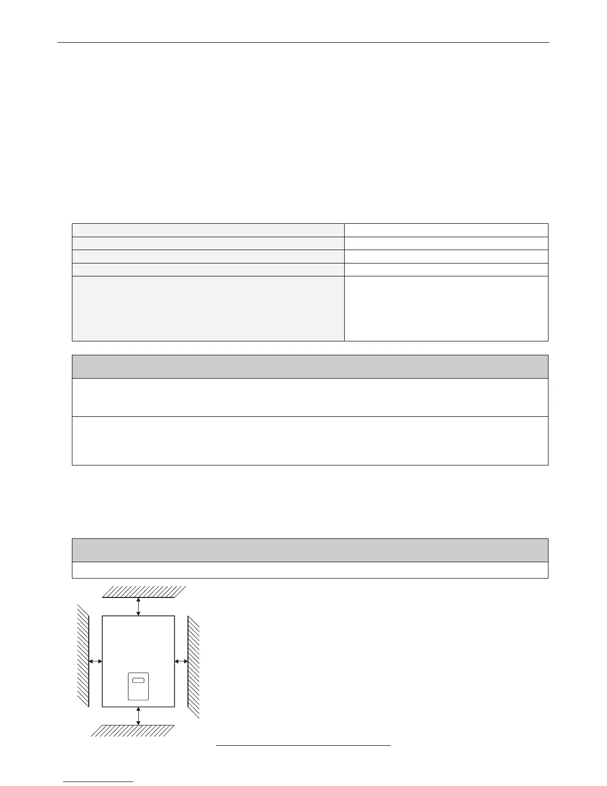
▪ Beside the side walls at least 50mm, below and above the unit at least 200
mm free space must be provided.
▪ If the device is built in closed control cabinet, overheating of the inside room
must be prevented with proper ventilation!
▪ The slots for fresh air and used air must be held free to assure proper
ventilation. The filters of the slots must be cleaned regularly!
▪ At IP54 versions the cooling is facilitated with heatsinks of increased size
that must be placed outside the cabinet, with maintaining the IP54
protection!
▪ On demand the manufacturer builds the equipment in a cabinet of proper
size.
▪ At types with forced ventilation the inlet openings should be on the bottom
side, the ventilated outlets on the upper side (possible diagonally)