H - I - J FREQUENCY CONVERTERS INSTRUCTION MANUAL 0,55 ÷ 200 kW
- 14 -
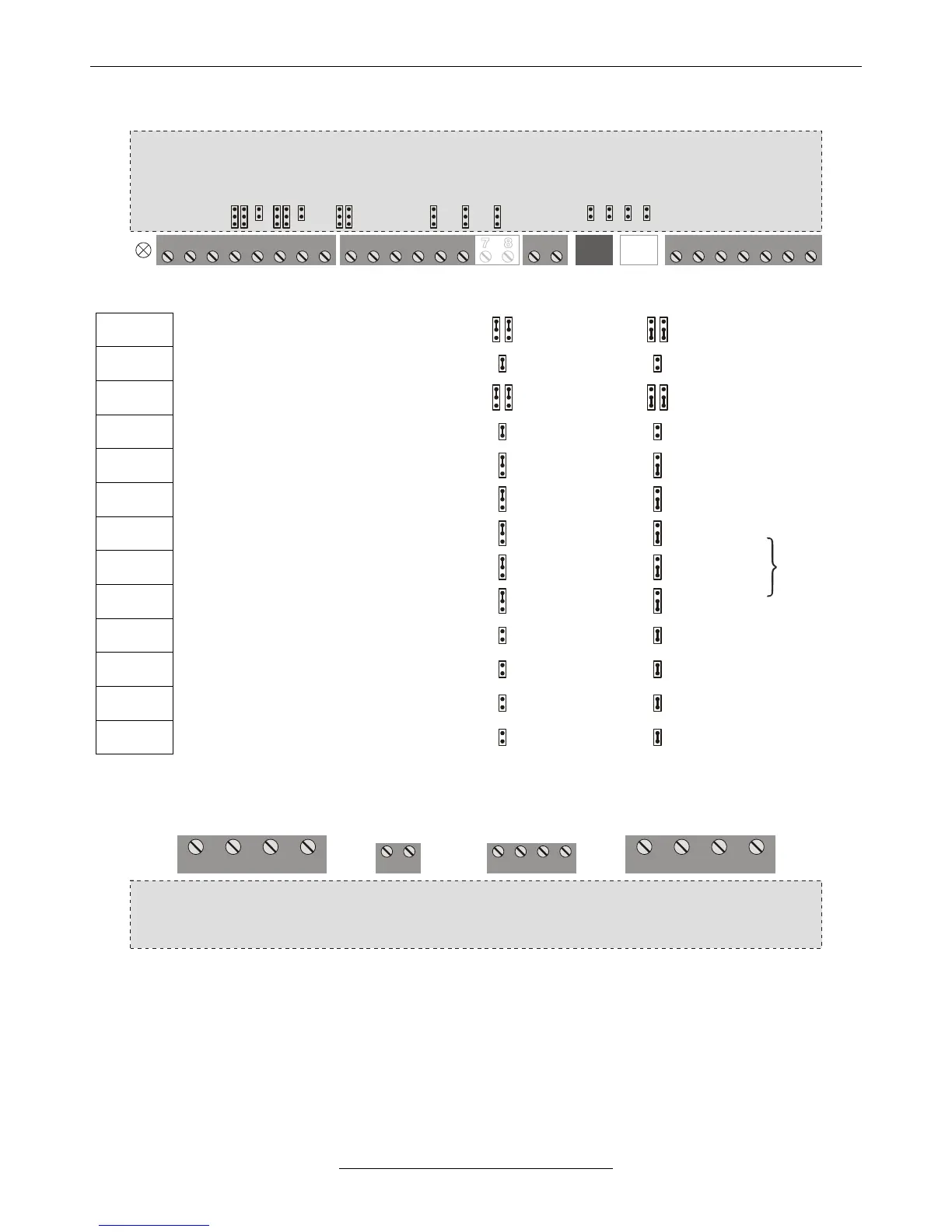
• Jumper settings
11 22 3 4 5 6 71 2 3 4 5 6 7 8
VLD / VHD frequency converter
K1
K2
K3
A1P
A1N
A2P
A2N
AK1
AK2
DIF1
DIF2
1 2 3 4 5 6
RS1
RS2
CAN2
CAN1
Setting the analogue input 1
Setting the analogue input 1
Setting the analogue input 2
Setting the analogue input 2
Setting the analogue output 1
Setting the analogue output 2
Setting the digital input 1-4
Setting the digital input 5-6
Setting the digital input 7-8 (option)
CAN1 line termination (200Ω) (option)
CAN2 line termination (200Ω) (option)
Terminal serial line termination (200Ω) (option)
System serial line termination (200Ω) (option)
• High voltage terminal block
U V W PE L1 L2 L3 PE
MOTOR
LINE
VLD / VHD frequency converter
R BRAKE FAN
Ventilator terminal block (3 x 400 V AC, switched together with the cooling ventilators of the frequency converter).
Available for connecting external cooling ventilator (e.g. for cooling the control cabinet), for models VHD 45 to 250
(option)
At models VHD 90 to 250, PE will be connected to a grounding screw.