H - I - J FREQUENCY CONVERTERS INSTRUCTION MANUAL 0,55 ÷ 200 kW
- 17 -
OPERATING THE CONVERTER
The source of the reference signal can be:
▪ external or front panel potentiometer,
▪ 0÷10 V,
▪ 4÷20 mA (0 ÷ 20 mA),
▪ front panel controlling terminal,
▪ external or front panel operating terminal (varying with the type),
▪ external or front panel programming terminal (varying with the type),
▪ RS 485 serial line,
▪ CAN bus,
▪ motor potentiometer
The source of the logical control signals can be:
▪ terminal blocks,
▪ front panel controlling terminal,
▪ external or front panel operating terminal (varying with the type),
▪ external or front panel programming terminal (varying with the type),
▪ RS 485 serial line,
▪ CAN bus
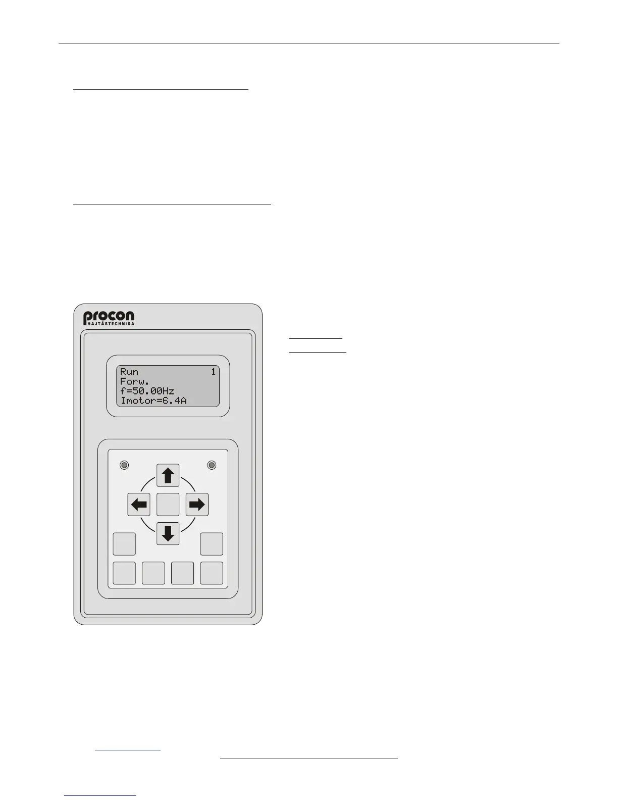
• Programming terminal
▪ It comprises a 4x16 character display and 11 push buttons in
two groups.
Upper group: , , , , DISPLAY, ESCAPE, ENTER,
Bottom group: JOG, DIRECTION, START, STOP.
Operation of the push buttons of the upper (programming)
group:
The push buttons of the upper group permit entering and selecting
data in the Parameter setting mode and in the Display mode.
Operation of the push buttons of the bottom (control) group:
The push buttons of the bottom group permit controlling the
operation of the frequency converter if the terminal has been
preset for the control. The bottom four push buttons work
independently from the upper ones. Therefore if the terminal is
the preset operating control, the motor can be stopped or
started etc. even during entering data.
▪ Default setting in Display mode
(The structure of displaying can optionally be varied: in any line
any parameter can be displayed.)
In line 1: the three parts of the status are displayed:
- Motor status: Run / Stop,
- Dynamic status acknowledgement (e.g. I limit),
- Identification of the frequency converter (e.g. 1).
In line 2: Direction Forw. / Backw.
In line 3: Frequency (e.g. f=50.00Hz),
In line 4: Motor current (e.g. Imotor=6.4A)
▪ It can be used as a built-in unit or in casing as a stand alone unit.
• Operating from the computer
The frequency converter can be connected to the computer through RS485-T line using RS 232 / 485 or USB / RS
485 adapter (interface).
Here the TermOnly program permits setting the frequency converter from the computer and provides a user
interface with the same look as that of the programming terminal.
The ProContact program beyond handling the frequency converter permits reading out, modifying and archiving the
actual parameter set as well as reading out and archiving the event- and error log.
Both programs are available on CD as attachment of the adapter (interface) unit or can be downloaded
from www.procon.hu.